A replacement capacitor can match the original part’s size, nominal capacitance and voltage rating yet give your power rail less capacitance in operation. Before approving the substitution, check MLCC DC bias: in a multilayer ceramic capacitor (MLCC), a steady direct-current (DC) voltage can change the capacitance available to the circuit.
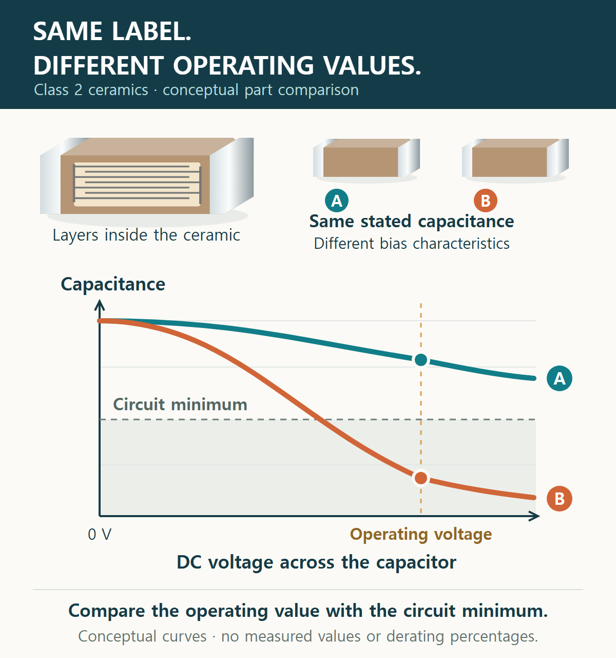
An MLCC stacks ceramic dielectric layers between metal electrodes. DC bias means the steady voltage across it. For many high-capacitance ceramic parts, that voltage changes the capacitance available to the circuit. The selection question is: does this exact part still meet the circuit’s capacitance requirement under its operating conditions?
- Nominal capacitance describes a specified measurement condition.
- Voltage rating and capacitance retention answer different questions.
- Compare exact part numbers, then verify the assembled circuit.
1. What changes inside the ceramic
High-dielectric-constant ceramics provide a large capacitance in a small package. These are commonly called Class 2 materials; X5R and X7R are familiar temperature-characteristic codes in this group. Their capacitance can fall as the applied DC voltage rises. Murata explains this bias effect and distinguishes it from temperature-compensating ceramics such as C0G, a Class 1 characteristic code.
The material’s electric polarization changes with the applied field. A steady bias can reduce its response to a small changing voltage. Here, effective capacitance means the capacitance available for those small changes around the operating voltage. A lower value under bias can be normal material behavior; the observation alone does not establish a defective capacitor.
TDK’s ceramic-capacitor primer explains why dielectric type, construction and applied field matter. Class 1 ceramics offer more stable capacitance, while Class 2 ceramics allow higher capacitance density. The choice depends on the circuit’s required capacitance, available space and operating conditions.
2. Read the curve for the exact part
A voltage rating sets an operating limit under specified conditions. It does not promise that nominal capacitance remains available below that limit. A higher-rated candidate may help, but its rating alone cannot tell you how much capacitance it retains.
Open the manufacturer’s data for each complete part number. Find the curve’s reference value: a percentage change may be relative to an initial measured value, rather than a guaranteed minimum. Record temperature, measurement frequency and AC (alternating current) test amplitude, meaning the small changing voltage used during measurement. Compare candidates under matching conditions.
Murata states that its design tool can compare part numbers and display changed measurement conditions. Such data helps selection. Before treating a curve as an acceptance limit, establish whether it is typical characterization, simulation or guaranteed specification.
3. Turn the data into a selection decision
Engineering implication: if a circuit needs a minimum output capacitance, a nominal-value match is insufficient evidence for a substitution. Use the controller’s requirements and the capacitor’s operating data together. The table below is a practical screening method, not a universal derating rule.
| What you have | What to check next |
|---|---|
| Only nominal capacitance and tolerance | Bias data at the voltage across the capacitor |
| The same X5R or X7R code | Each exact part’s curve and measurement conditions |
| A higher voltage rating | Actual retained capacitance; do not assume an improvement |
| A typical curve that appears sufficient | Tolerance, temperature, aging and the guaranteed limits available |
| A replacement that passes the data check | Circuit behavior on the assembled board |
Keep nominal tolerance, temperature change, aging and bias distinct in your calculation. Check which effects a supplied model already includes before applying additional allowances. If combined-condition data is missing, ask for it or measure it; multiplying unrelated percentage limits does not establish a manufacturer’s guaranteed minimum.
For an output capacitor, the next circuit checks may include voltage ripple (small periodic voltage variations), response to a sudden load change and control-loop stability (avoiding sustained oscillation in the regulator’s feedback system). A capacitance estimate alone cannot establish all three. Test the intended capacitor arrangement and board layout across the relevant supply, load and temperature conditions.
4. Keep a small evidence packet with the replacement
- Record the original and proposed full manufacturer part numbers.
- Save each curve, its download date and its measurement conditions.
- State the voltage across the capacitor and the circuit’s required capacitance range.
- Separate typical estimates from guaranteed limits and unresolved margins.
- Record the board checks and the conditions under which the replacement is accepted.
This checklist applies wherever components are sourced. Keep it with the substitution record so a later purchasing change preserves the engineering decision. For the broader substitution process, see Beyond Pin Compatibility.
Selected primary sources
- Murata: DC bias characteristics — material behavior and ceramic types.
- TDK: Ceramic Capacitors, Part 3 — voltage rating, dielectric type and bias.
- Murata: data under changed measurement conditions — part comparisons and design-tool data.
Sources checked 4 November 2026. This is a general selection guide; exact component specifications and circuit requirements govern acceptance.
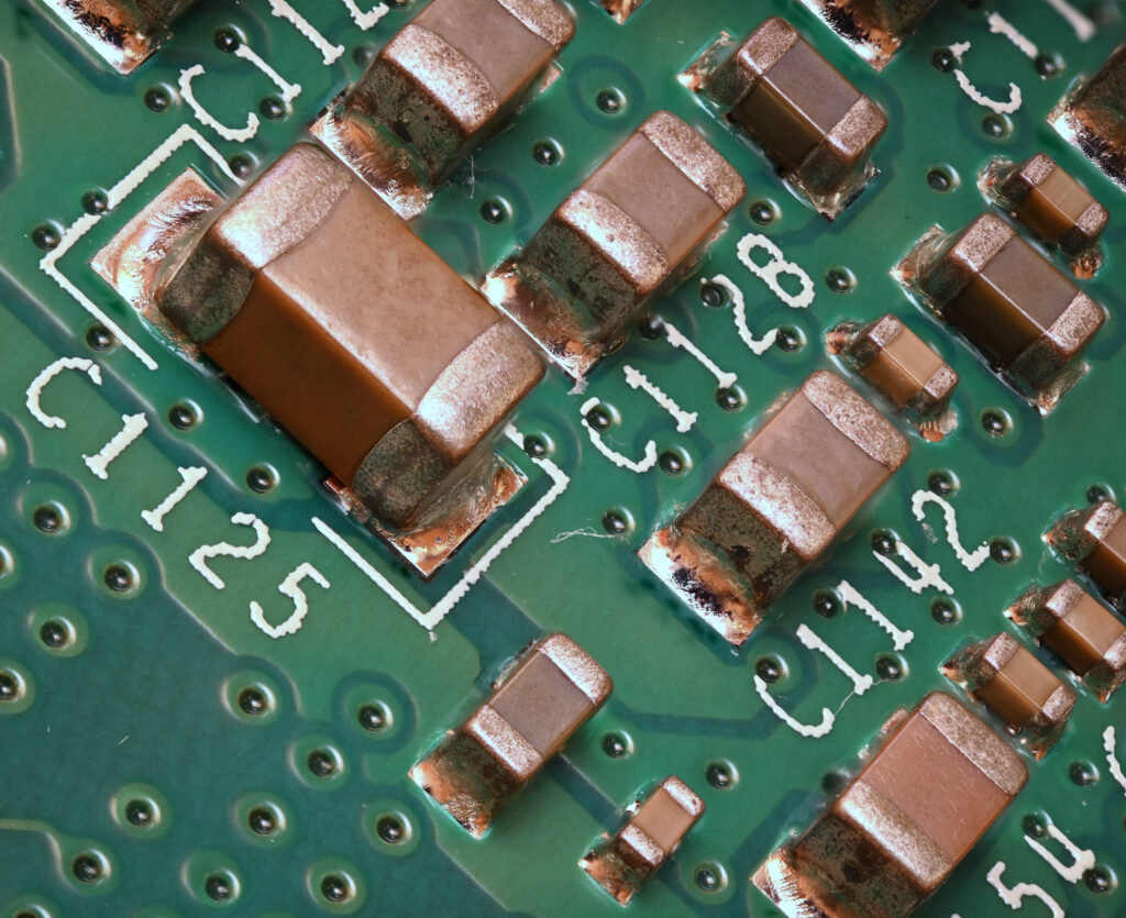
Featured photo: Many different SMD capacitors — Phiarc / Wikimedia Commons, CC BY-SA 4.0. Photographed 13 March 2023. Original photograph reused; display versions may be resized or cropped. The photograph and any crops remain under CC BY-SA 4.0.
Please link to this article when sharing. Contact us for permission to republish the full article.