
Why inrush control, fast fault isolation, and precision telemetry—not conversion efficiency alone—will decide whether megawatt AI racks are serviceable
A compute tray slides toward an energized high-voltage rack boundary. Before its converter can power a single accelerator, another system must decide whether the connection is valid, control the charge entering the tray, verify that voltage and current behave as expected, enable the main path, and remain ready to disconnect it again.
That boundary is usually described as hot swap. In an emerging 800 VDC architecture, the name sounds smaller than the job.
The most revealing number in the 800 VDC data-center discussion is not an efficiency percentage. It is current.
At an idealized 1 MW, a 54 V bus corresponds to roughly 18.5 kA. At 800 V, the same power corresponds to 1.25 kA. Real systems require conversion-loss, redundancy, transient, and distribution margins, but the first-order relationship explains the architectural pressure: as rack power approaches the megawatt class, raising distribution voltage sharply reduces the current that conductors, connectors, and busbars must carry.
NVIDIA says a 1 MW rack implemented around 54 V could require up to 200 kg of copper busbar. Its proposed 800 VDC architecture is intended to support 1 MW racks and beyond, with full-scale production aligned to its Kyber generation in 2027. This is a roadmap, not evidence that 800 VDC has already displaced today’s rack architectures. But during 2026, the supporting semiconductor ecosystem began moving from presentation diagrams toward concrete reference hardware.
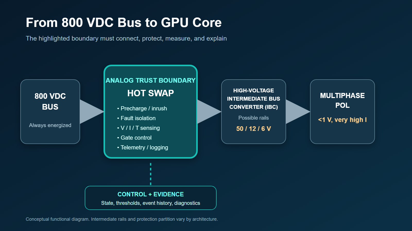
The visible part of that transition is the power switch: SiC and GaN devices converting energy at higher voltage and density. The less visible—and potentially more differentiated—part is the analog control boundary at relevant rack or compute-tray interfaces in proposed architectures. At 800 VDC, hot swap is no longer just a convenience circuit. It must manage stored energy, control inrush, distinguish faults from workload transients, isolate a failing tray, and report what happened while supporting continued operation elsewhere in the rack.
That makes hot swap the analog control plane of the emerging 800 V AI rack. We use “analog control plane” as an editorial lens for the coordinated protection, sensing, isolation, telemetry, and state-management functions—not as an established industry category.
Key insights
- The 800 V transition is a protection, sensing, and serviceability problem as much as a conversion-efficiency problem.
- Reference architectures disclosed in 2026 point to new IC content in hot-swap control, isolated sensing, gate drive, telemetry, digital power management, and fault coordination.
- Wide-bandgap switches do not remove the need for precision analog. Faster edges and greater fault energy can make sensing, isolation, timing, and safe shutdown harder.
- The opportunity is emerging, not mature: 48/54 V will coexist with 800 V, and important protection and interoperability questions remain open before broad deployment.
The current wall behind the voltage transition
Power is voltage multiplied by current. For a simple DC comparison:
I = P / V
At 1 MW:
| Distribution voltage | Idealized current | What the number illustrates |
|---|---|---|
| 54 VDC | 18,519 A | Extreme conductor, connector, busbar, and thermal pressure |
| 800 VDC | 1,250 A | About 14.8 times less current at equal power |
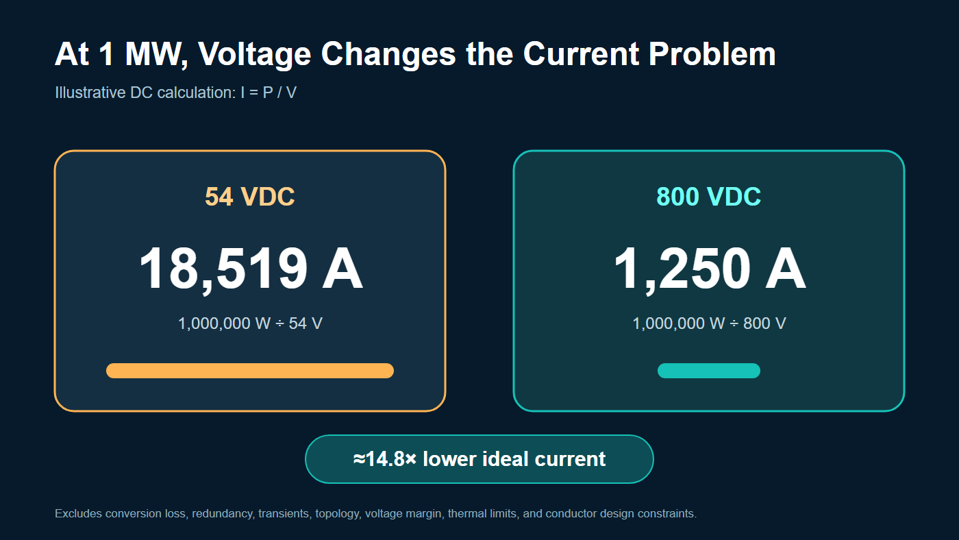
These are explanatory calculations, not rack-design values. They exclude conversion losses, redundancy, dynamic load margins, topology, and conductor-temperature limits. Their purpose is to show why incremental improvement at 54 V eventually collides with physical packaging.
NVIDIA identifies rack space, copper mass, and repeated power conversion as limits of the existing approach. Its proposed architecture centralizes conversion to 800 VDC and moves high-voltage DC closer to the compute rack. High-voltage intermediate-bus converters then step the bus down to rails such as 50 V, 12 V, or 6 V before multiphase converters deliver sub-1 V power to accelerators.
The exact winning conversion path remains unsettled. That is clear from the architectures shown in 2026:
- Texas Instruments demonstrated an 800 V hot-swap stage, an isolated 800 V-to-6 V converter using integrated GaN stages, and a 6 V-to-sub-1 V multiphase stage.
- STMicroelectronics presented 800 V-to-50 V, 12 V, and 6 V approaches, implying that different intermediate rails may coexist by server form factor.
- Infineon introduced 800 V-to-50 V and 800 V-to-12 V high-voltage intermediate-bus reference designs, as well as an 800 V-connected high-voltage battery-backup reference design.
- Analog Devices described its development of high-voltage hot-swap and DC-DC solutions for the NVIDIA MGX ecosystem.
These announcements are best read as evidence of architecture and ecosystem maturation. Several are reference designs or solutions under development, not proof of broad production deployment.
Why 800 V changes the hot-swap problem
In a conventional hot-swap event, a technician inserts or replaces a server tray while the rest of the rack remains powered. The controller limits the current charging the tray’s input capacitance, verifies that startup conditions are acceptable, and then enables the main power path.
At 800 VDC, the same sequence operates at a much higher energy boundary. The controller and surrounding power stage may need to coordinate five functions:
- Detect and qualify insertion. Confirm connector engagement, polarity, bus conditions, and local readiness.
- Precharge the tray. Charge input capacitance through a controlled path so that an empty capacitor bank does not appear as a short circuit.
- Validate the transition. Check voltage rise, current, timing, temperature, and abnormal leakage before enabling the main switch.
- Connect and monitor. Turn on the primary path while continuously measuring current, voltage, power, and thermal conditions.
- Contain faults. Detect a short, overload, arc-related abnormality, failed converter, or unsafe thermal condition; then isolate the tray and preserve evidence for diagnosis.
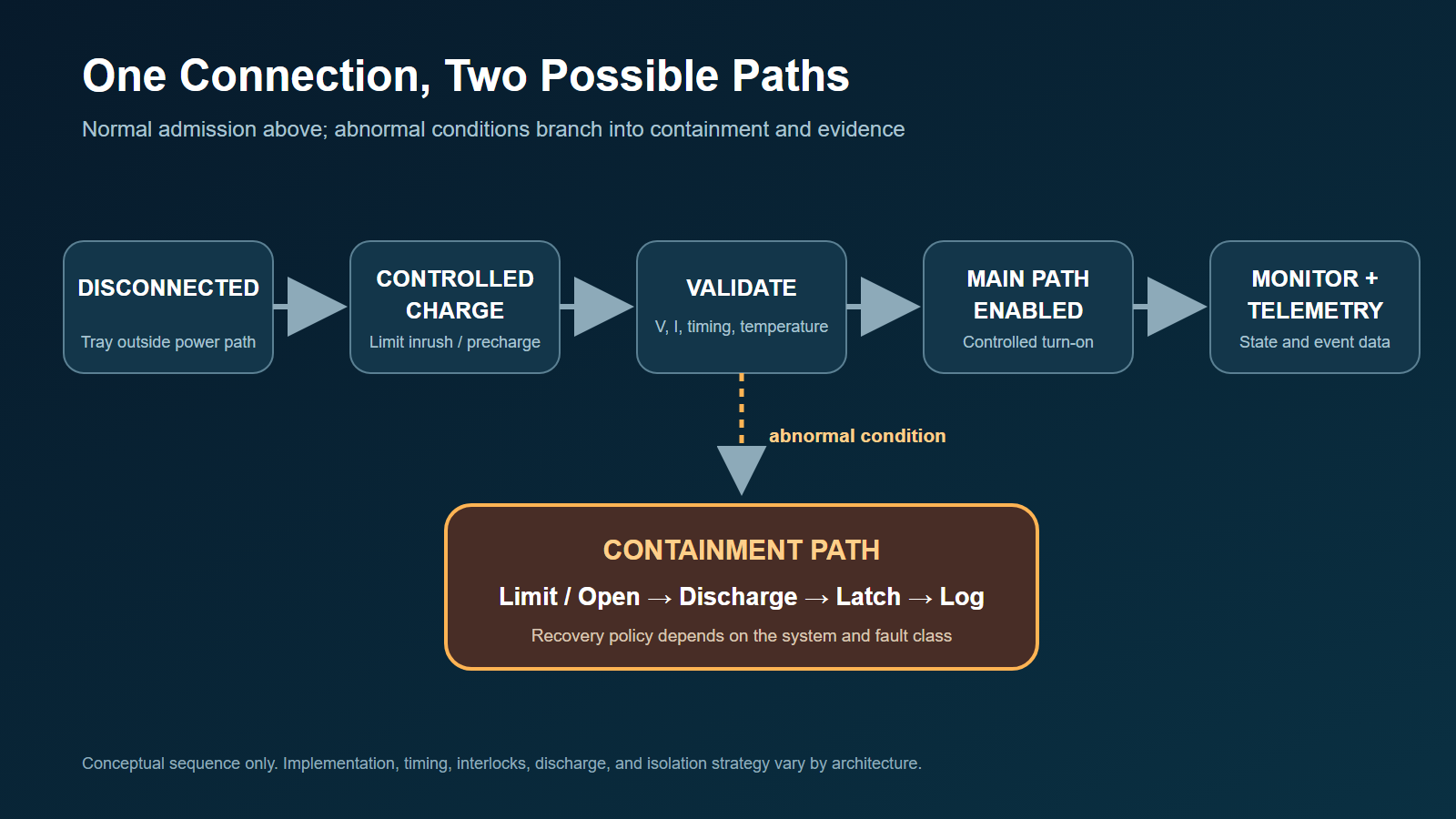
This is why “hot swap” undersells the function. The block sits at the boundary between an always-energized distribution bus and a removable high-power load. It acts as an analog front end, a gate-control system, a protection state machine, and a telemetry source.
Four analog design problems hiding inside the block
1. Inrush control becomes an energy-management problem
The input capacitance of a compute tray must be charged. A simplified stored-energy relationship is:
E = 1/2 × C × V²
For illustration, 100 µF charged to 800 V stores 32 J. During a controlled linear charge, the series switch can dissipate energy on the same order as the energy ultimately stored in the capacitor. This is why a hot-swap switch cannot be selected only from breakdown voltage, current rating, and low on-resistance; its pulsed safe operating area must also cover startup and fault cases.
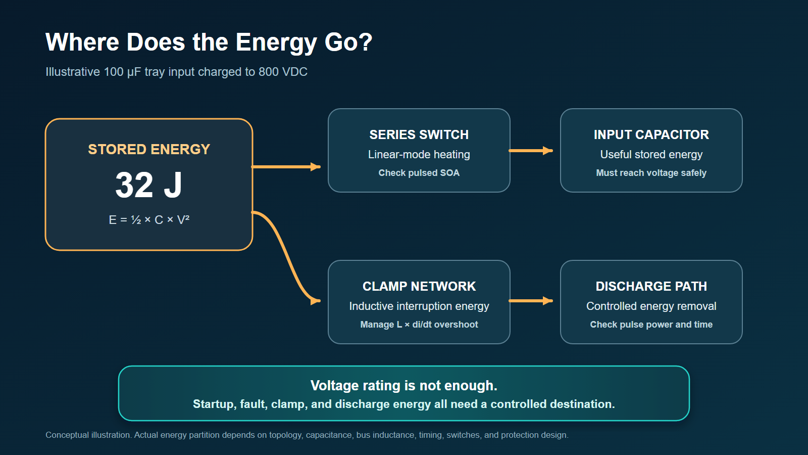
Because energy rises with the square of voltage, capacitance charged to 800 V represents a different stress class from the same capacitance charged to 48 or 54 V. Real architectures may partition capacitance, use sidecars, or employ intermediate conversion, but the controller still needs a controlled startup trajectory.
The design question is not simply “how much current is allowed?” It is whether the pass element, precharge path, connector, and downstream converter remain inside their safe operating areas throughout startup and abnormal conditions.
2. Fast trip must not become false trip
AI loads are dynamic. A protection circuit must distinguish a genuine fault from expected startup behavior, converter transients, and workload-driven current changes. A threshold that is too slow can expose switches and conductors to destructive energy. A threshold that is too aggressive can disconnect healthy compute during a legitimate transient.
That tension creates room for multi-level protection: fast analog comparators for severe faults, filtered or digitally supervised thresholds for slower overloads, programmable timing, and coordinated action with the downstream converter.
Fast protection and slower telemetry should remain distinct. A management ADC or PMBus transaction can reconstruct an event, but it should not be the only mechanism protecting a switch during a rapidly developing short circuit.
3. Precision measurement must survive a hostile switching environment
The system may need to measure small changes in current or voltage while nearby GaN or SiC stages produce rapid common-mode transitions. Current-sense amplifiers, isolated sensors, ADCs, references, and communication interfaces therefore face a combined accuracy-and-immunity problem.
Useful performance is not captured by DC accuracy alone. Bandwidth, propagation delay, common-mode transient immunity, isolation rating, offset drift, conductor loss, and diagnostic coverage all affect whether the measurement can protect the system and support telemetry.
4. Isolation and control partitioning become architectural choices
An 800 V or ±400 V architecture does not automatically dictate one grounding or control scheme. The controller may be referenced to the high-voltage domain, communicate across an isolation barrier, or divide fast analog protection from supervisory digital control.
That partition affects bias power, gate-drive method, communication, creepage and clearance, fault behavior, and test strategy. It also influences what should be integrated into one IC and what should remain separated for voltage, thermal, or qualification reasons.
DC interruption adds another system-level constraint: unlike AC, a DC arc does not receive a natural current zero every half-cycle. Semiconductor turn-off, connector design, upstream breakers or fuses, discharge paths, enclosure, interlocks, and service procedures must therefore be coordinated. “Hot swappable” does not mean exposed 800 V contacts are touch-safe.
From protection event to operational data
At megawatt rack scale, protection without observability is incomplete. A trip flag tells an operator that something failed; timestamped voltage, current, power, and temperature data can help explain why.
An advanced hot-swap subsystem can potentially provide:
- Input-voltage and tray-current telemetry
- Power and energy accumulation
- Peak and average measurements
- Temperature and thermal-warning data
- Startup timing and precharge diagnostics
- Fault classification and event logging
- Communication through a management interface such as PMBus
These capabilities can support service decisions and fleet-level analysis. However, “predictive maintenance” should be treated as a possible use case, not a proven result until operators publish field evidence.
Where analog IC suppliers can differentiate
The 800 V opportunity is not confined to the highest-voltage power device. The control stack may include:
| Function | Potential IC differentiation |
|---|---|
| Hot-swap controller | Floating control, programmable startup, fast fault response, redundant gating |
| Gate driver | High CMTI, controlled turn-off, fault feedback, isolation integration |
| Current and voltage sensing | Accuracy across dynamic range, bandwidth, low loss, reinforced isolation |
| Telemetry ADC and monitor | Synchronized acquisition, event capture, PMBus, diagnostics |
| Bias and isolated power | Compact isolated supply for floating control domains |
| Digital power controller | Sequencing, conversion coordination, fault policy, firmware observability |
| Intermediate-bus controller | High conversion ratio, transient response, multi-rail flexibility |
| Multiphase point-of-load control | Kiloamp-class transient delivery near the accelerator |
This favors suppliers that can reason across the whole power path. ADI’s July 2026 completion of its Empower Semiconductor acquisition is one business signal: the company is linking protection and high-voltage power management with integrated voltage regulation and silicon capacitors closer to the processor.
The strategic question is therefore larger than who owns the best 650 V or 1,200 V switch. It is who can make the entire path—from energized bus to sub-1 V core—measurable, diagnosable, qualified, and supportable within a coordinated system-safety design.
The design tensions that remain unresolved
| Tension | Question that must be answered |
|---|---|
| Fast trip vs nuisance trip | How does the system separate a destructive fault from startup or workload transients? |
| Density vs isolation | How are creepage, clearance, thermal paths, and service access preserved? |
| Accuracy vs switching immunity | Can small signals remain trustworthy during high dV/dt events? |
| Switch SOA vs fault energy | Can the power path survive long enough to shut down predictably? |
| Integration vs flexibility | Which functions belong in the controller IC, power module, or system MCU? |
| Local autonomy vs rack coordination | Which faults should a tray handle alone, and which require upstream action? |
| Open ecosystem vs proprietary optimization | Which interfaces and protection behaviors must be standardized? |
These are not secondary implementation details. They will influence component selection, topology, process technology, packaging, test coverage, field diagnostics, and ultimately whether live service at 800 V is economically practical.
What a design-win review should request
The public roadmap is moving faster than public production evidence. A buyer evaluating an 800 V protection solution should therefore ask for proof at the system boundary, not only a controller datasheet or converter efficiency number:
- Nominal, maximum, surge, and fault-voltage envelope
- Startup, shutdown, retry, and output-discharge waveforms
- Switch safe-operating-area and fault-energy analysis across temperature
- Startup-into-short, abrupt-short, gradual-overload, and insulation-fault results
- Current and voltage telemetry accuracy, bandwidth, latency, and CMTI behavior
- Isolation architecture, lifetime assumptions, and accumulated leakage-current analysis
- Coordination with upstream breakers or fuses and downstream converter UVLO
- Fault-latch, event-log, timestamp, and recovery behavior
- Connector, interlock, and service-procedure assumptions
- Clear status: concept, reference design, orderable silicon, qualified component, interoperable system, or field deployment
That evidence ladder matters because a demonstrated reference design can prove feasibility without proving manufacturing readiness, multi-vendor interoperability, field reliability, or safe service procedures.
The ChinaSemiOps view: follow one watt—and one fault
A useful way to evaluate the emerging supply chain is to follow one watt from the facility bus to the GPU core. At each conversion boundary, ask which device performs the power conversion, which IC controls it, which sensor verifies it, and which protection element contains a failure.
Then follow one fault in the opposite direction. If a compute-tray converter fails short, what detects it first? How much energy is available before isolation? Which switch must survive the interruption? What telemetry remains after shutdown? Does the fault stay local, or does it propagate into the rack or sidecar?
This two-direction analysis prevents the market discussion from collapsing into a GaN-versus-SiC comparison. Wide-bandgap devices matter, but they operate inside a system whose commercial value depends on protection, control, observability, packaging, and qualification.
Reality check: 800 V is an emerging frontier
Three cautions should remain visible:
- The deployment horizon is forward-looking. NVIDIA aligns full-scale 800 VDC production with its Kyber rack generation in 2027.
- 48/54 V is not disappearing. Existing infrastructure and intermediate-bus designs will keep it relevant, and hybrid architectures are part of the migration path.
- Reference-design numbers are not fleet results. Efficiency, density, copper, maintenance, and TCO claims should remain attributed to the organizations publishing them until independent operating data becomes available.
The transition is nevertheless important because it changes where semiconductor value can accumulate. At 800 VDC, reliable serviceability requires more than an efficient converter. It requires an analog control boundary capable of admitting power safely, observing it precisely, and disconnecting it decisively.
That is why hot swap may become one of the defining analog subsystems of the megawatt AI rack.
Selected public sources
- NVIDIA, “800 VDC Architecture Will Power the Next Generation of AI Factories,” May 20, 2025: https://developer.nvidia.com/blog/nvidia-800-v-hvdc-architecture-will-power-the-next-generation-of-ai-factories/
- Texas Instruments, “TI unveils complete 800 VDC power architecture,” March 16, 2026: https://www.ti.com/about-ti/newsroom/news-releases/2026/2026-03-16-ti-unveils-complete-800-vdc-power-architecture-for-future-generation-ai-data-centers-with-nvidia.html
- Analog Devices, “Protection and Telemetry in AI with 800 V Hot Swap,” February 2026: https://www.analog.com/en/resources/analog-dialogue/articles/protection-and-telemetry-in-ai.html
- Analog Devices, “Powering the Next Generation of NVIDIA AI Factories with MGX,” May 28, 2026: https://www.analog.com/en/newsroom/press-releases/2026/5-28-2026-powering-next-generation-nvidia-ai-factories-mgx.html
- Infineon, CoolGaN HV-IBC reference designs, March 17, 2026: https://www.infineon.com/de/technology-news/2026/infpss202603-067
- Infineon, 24 kW SiC-based HV-BBU reference design, June 2, 2026: https://www.infineon.com/technology-news/2026/infpss202606-093
- STMicroelectronics, 800 VDC-to-50 V/12 V/6 V architectures, March 17, 2026: https://newsroom.st.com/media-center/press-item.html/t4766.html
- Open Compute Project, “Delivering an Open Data Center Ecosystem for AI,” April 29, 2026: https://www.opencompute.org/index.php/blog/delivering-an-open-data-center-ecosystem-for-ai
This article discusses an emerging architecture and public reference material. It is not a recommendation for a specific component, topology, supplier, safety design, or production implementation.