For most of the last decade, the central debate in power semiconductors was which material would win: silicon carbide or gallium nitride, and when would they displace the silicon IGBT. That debate has not been settled, but in the hardest high-voltage, high-current applications it is increasingly the wrong question.
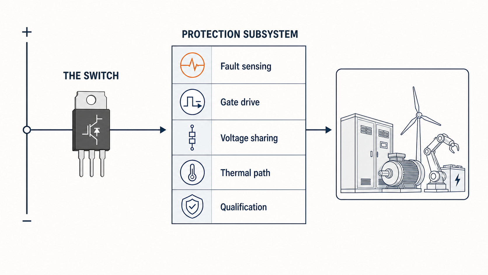
As systems reach multi-kilovolt operating voltages and hundreds of amps of continuous current, the engineering challenge is shifting. The question is no longer only whether a given semiconductor can switch efficiently at these voltages. The question is whether the protection architecture around it — fault detection, current interruption, series and parallel device sharing, gate-drive isolation, and mission-profile qualification — can be made to work reliably. In several important ways, solving those problems is harder for the newest semiconductors than it was for the silicon devices they are intended to replace.
At HV/HC scale, the device is only the entry point. The defensible value increasingly sits in the protection, packaging, and qualification stack.
Why DC Fault Interruption Is Uniquely Difficult
In an alternating-current system, fault current crosses zero 100 to 120 times per second. A mechanical breaker exploits that natural zero to extinguish the arc and open the circuit. A direct-current system has no natural zero crossing. A DC circuit breaker must manufacture an artificial current zero, diverting fault energy into a commutation branch and dissipating the stored inductive energy, typically into a metal-oxide varistor clamp.
The energy the clamp must absorb scales with the loop inductance and the square of the peak fault current. At multi-kilovolt bus voltages with low-inductance connections carrying hundreds of amps, fault current can rise at kiloamperes per microsecond. A protection circuit that detects and interrupts within one microsecond faces a fundamentally different fault-energy budget than one operating in milliseconds — and that speed difference is the core argument for semiconductor-based DC circuit breakers.
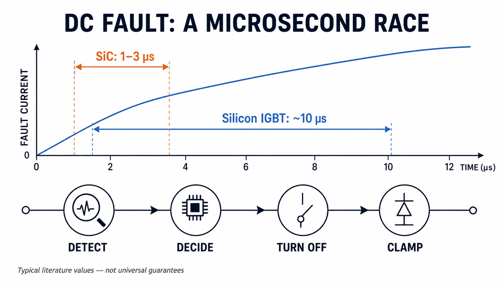
Typical literature values, not universal guarantees: SiC protection often has only a 1–3 µs action window, making detection, decision, turn-off, and energy clamping a tightly coupled sequence.
Research presented at APEC 2026 demonstrated a series-stacked switching architecture — a SiC JFET super-cascode using five 1.2 kV JFETs controlled by a 1.2 kV MOSFET — that achieved 7.2 kV blocking voltage and experimentally interrupted one kiloampere at 7.8 kV. This is a conference research result, not a commercial product, but it establishes that semiconductor-based high-voltage interruption at these levels is physically achievable. (APEC 2026 paper)
The Penalty Solid-State Pays
The speed advantage of semiconductor interruption does not change the physics of being permanently in the current path. A solid-state circuit breaker conducts full load current continuously. In some studied DC-breaker topologies and duty regimes, published analyses attribute roughly 30 to 35 percent of total system losses to the semiconductor’s on-state conduction drop — a permanent efficiency and cooling penalty that a closed mechanical contact avoids.
For SiC specifically, the fault-handling picture is more nuanced than the switching-performance narrative suggests. The short-circuit withstand time — how long a device can survive a bolted fault before thermal destruction — is typically one to three microseconds for SiC MOSFETs, versus approximately ten microseconds for a comparably rated silicon IGBT, according to published characterization work. SiC operates at five to ten times higher current density under short-circuit, with lower thermal mass per die area.
Conventional desaturation protection circuits developed for the IGBT cannot be directly applied to SiC modules. The higher di/dt and weaker short-circuit ruggedness of SiC require new sub-microsecond, isolated fault-sensing solutions. The design window between fault occurrence and device destruction is narrower than in the technology being replaced. The protection difficulty argument cuts in both directions: SiC enables faster switching, but its shorter fault-withstand window is directly penalized by breaker duty.
Silicon Is Not Standing Still
An important counter-narrative emerged in February 2026. Hitachi Energy and Pakal Technologies announced a collaboration to integrate Pakal’s Insulated Gate Turn-Off thyristor — the IGTO — into silicon power modules rated at 3.3 kV and above. Pakal claims approximately 30 percent lower conduction losses than IGBTs at high current and temperature while maintaining compatibility with existing module architectures. That figure is vendor-stated and has not been independently validated. Target applications include rail traction, renewable energy, grid storage, and high-power infrastructure.
The IGTO joins the established IGCT — integrated gate-commutated thyristor — as evidence that silicon is actively evolving in exactly the voltage and current class where silicon carbide modules are advancing. Published reviews of IGCT technology note lower on-state voltage and superior short-circuit ruggedness compared to IGBTs, with the devices preferred above approximately five megavolt-amperes at low switching frequency.
The breaker duty is a near-zero switching frequency application: the device conducts DC and switches once per fault event. The metrics that matter most are conduction loss and short-circuit ruggedness. On both counts, silicon holds advantages for high-current, low-switching-rate operation, while SiC’s headline advantage — high-frequency switching efficiency — is largely irrelevant to the duty and its fault-withstand weakness is directly exposed by it.
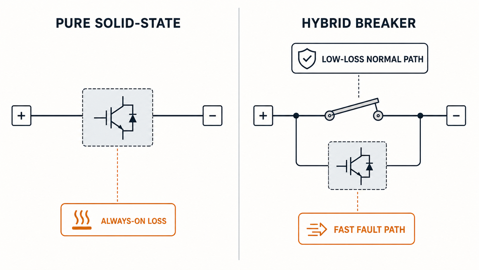
At transmission-level high-voltage direct current, published architectures and leading demonstrations favor hybrid breakers: mechanical main conduction paths with negligible on-state loss, plus solid-state semiconductor commutation branches that handle the microsecond interruption event. The semiconductor provides the speed; the mechanical path carries the continuous current.
The topology tradeoff: pure solid-state puts the semiconductor in the current path continuously; hybrid designs separate the low-loss normal path from the fast fault-commutation path. The best choice still depends on voltage, duty cycle, and system requirements.
Series and parallel connection of multiple SiC devices — required to reach the highest voltages and currents — creates active engineering challenges. Voltage sharing in series-connected devices requires compensating for output-capacitance mismatch and gate-timing skew; the fastest-switching device in a string can momentarily see the full string voltage. Current sharing in parallel devices depends on threshold-voltage uniformity and layout symmetry of gate and power loops. Published surveys describe active balancing as an ongoing research area at kilowatt-class scale.
The qualification framework for medium-voltage DC solid-state circuit breakers does not yet have a mature, dedicated type-test standard. The IEC 62271 family addresses alternating-current switchgear, with IEC TS 62271-318:2024 covering DC switchgear at 100 kV and above. This leaves fault-interrupt endurance, isolation integrity, thermal-cycle qualification, and fail-safe behavior in the 1.2 kV to 6.6 kV range without a mature dedicated comparison framework, making procurement comparisons harder. This standards gap is a genuine adoption barrier independent of device performance.
Infineon states that its 1300 V HybridPACK Drive SiC module, FS01M9R13A7MA2B, can operate continuously up to 205 °C, above the typical 175 °C design point cited in the release. That is a product-rating claim, not proof of mission-profile lifetime at that temperature. Interconnect technology, cooling, derating, power cycling and qualification determine whether elevated-temperature capability becomes reliability margin, smaller thermal hardware or accelerated wear.
What This Means
Competitive differentiation at 3.3 kV and above is increasingly tied to the complete module stack: substrate choice, die-attach method, encapsulant and creepage design, integrated gate-drive, and qualification evidence including power-cycling endurance and partial-discharge data. These are not characteristics of a commodity switching die.
For power semiconductor participants across device design, module assembly, and system integration, the implication is that value in high-voltage, high-current infrastructure applications is tied to certified subsystem capability as much as to die performance or wafer capacity. Product availability and engineering samples are not deployment evidence. The absence of verified volume design wins in the reviewed public evidence is consistent with an early 3.3 kV SiC market, but it does not prove that no private adoption exists.
What Buyers and Partners Should Ask
Are there named production design wins, or only samples and demonstrations?
What short-circuit safe-operating-area and protection response-time evidence exists under the intended bus voltage, loop inductance and temperature?
How do conduction loss and total cooling cost compare with hybrid and mechanical alternatives under the real duty cycle?
What power-cycling, partial-discharge, isolation and fail-safe test data are available?
Which type-test and certification path will the buyer accept?
What mission-profile evidence supports operation above the conventional 175 °C design point?
The industry is not debating whether silicon carbide can switch at multi-kilovolt levels. The open questions are at the system level: whether solid-state protection architectures can match the conduction efficiency of mechanical and hybrid solutions in high-continuous-current applications; whether SiC’s shorter short-circuit withstand time can be addressed by fast enough fault detection in production designs; and whether the standards infrastructure for MVDC solid-state circuit breakers can mature to match the pace of product announcements. Silicon is actively evolving into the same voltage class, hybrid topologies remain the demonstrated solution at the highest power levels, and the qualification path is long. Those are the open questions that will determine the commercial trajectory of the category.
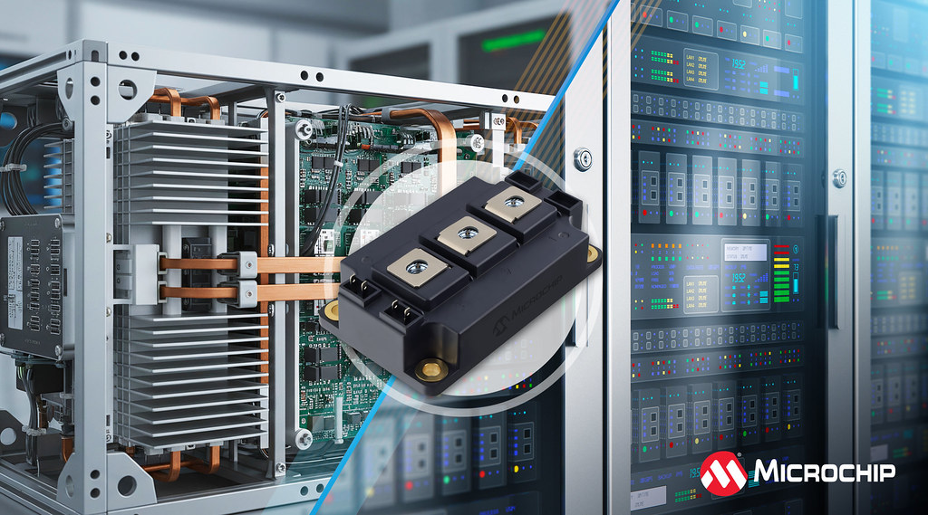
Featured image: Microchip 3.3 kV HV-D3 mSiC power module in a data-center power application. Image: Microchip Technology Inc. Official application image used for editorial coverage; source.