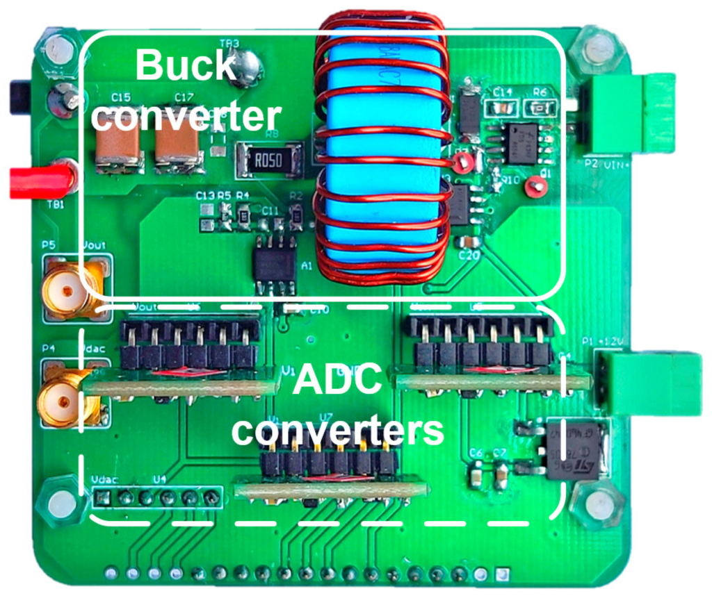
Power inductor current ratings can mislead when you replace a part in a 5 A step-down (buck) converter. Two candidates share a footprint and the same inductance (L), the property that makes a coil oppose changes in current, yet list different ratings.
Check two limits separately. Isat, the saturation current, is the direct current (DC) at which inductance has fallen by a stated amount; compare it with your peak current. Irms is a manufacturer's thermal rating from a stated test; compare it with root mean square (RMS) current, the steady current that heats a given resistance as much as your real, changing current does.
Three takeaways
- Isat is a test criterion, a specified drop in inductance, not a damage boundary. Inductance can already be lower before the current reaches it.
- Irms is a heating result under the manufacturer's stated conditions, not a promised temperature or current in your board.
- Compare your peak current (Ipk), the highest instant of inductor current, with the magnetic limit and your RMS current with the thermal one, then measure the assembled board.
Two ratings, two different limits
Coilcraft's application note on current and temperature ratings draws the split. It defines Isat as the current at which inductance falls a specified amount below its value with no DC current, a drop it attributes to core saturation. It defines Irms as the DC that raises the part's temperature a set amount above a 25 °C ambient (surrounding-air) temperature, which it attributes to resistive losses.
Coilcraft says a rating must name its measurement method and performance limit, and that different criteria lead to different conclusions; Würth Elektronik's note ANP138 says rated-current definitions still vary between manufacturers. Coilcraft adds that for some inductors Isat is below Irms, so the core saturates before the part reaches its temperature limit, while for many others heating limits first.
Check peak current against the inductance drop
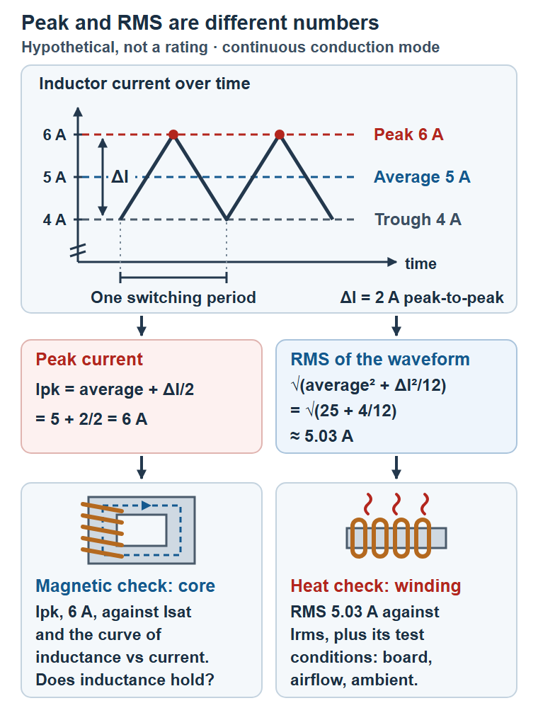
In a buck converter in continuous conduction mode (CCM), the inductor current never drops to zero. In steady state it ramps up and down around its average, Iavg, and the peak-to-peak current ripple (ΔI) is the gap between its highest and lowest values. For an approximately triangular, steady-state CCM current, the peak is Ipk = Iavg + ΔI/2.
Texas Instruments (TI) gives the same expression in application note SLVA477C, revised September 2026 (page 3, equation 4), for a buck converter with an integrated switch in CCM: the maximum switch current is half the ripple plus the maximum output current, the peak the inductor must withstand. TI adds that the inductor needs a higher current rating than that figure, because current rises as inductance falls.
Take a hypothetical example: 5 A average and 2 A peak-to-peak ripple. The current ramps between 4 A and 6 A, so Ipk is 6 A. Compare that with Isat and with the manufacturer's curve of inductance against current and temperature. Isat is one point on that curve, and inductance can already be lower before the current reaches it. This implies nothing about any real part's rating. Startup surges, load steps and fault current limits are separate events: evaluate each against the controller datasheet and your test procedure, and use the worst applicable peak rather than adding them to this steady value.
Check RMS current and the heat path
Heating follows the RMS current: square the current at each instant, average over a cycle, then take the square root. Coilcraft notes that an RMS value has the same resistive heating effect as the comparable DC value, including for triangular waveforms; it does not describe every loss. For an approximately triangular, steady-state CCM current like the one above, the waveform RMS, written IRMS(wave) to keep it apart from the catalog Irms rating, is √(Iavg² + ΔI²/12) = √(25 + 4/12) ≈ 5.03 A. Ripple barely changes the heating current here, though it added a full amp to the peak.
Then read the catalog conditions. Coilcraft determines Irms on a representative sample: a low DC bias is raised until the temperature rise reaches the limit, measured on top of the part in still air with no heat sinking, typically a 40 °C rise for power inductors. A data sheet's ambient range describes the surroundings, not the part.
Würth explains why the printed circuit board (PCB) matters: conductor width, thickness and surface area change how heat leaves the part. Its basic rated-current comparison assumes direct current without extra heat-generating parts; alternating current (AC), which varies over time, and the surroundings shift real temperatures.
A quick estimate, current squared times DC resistance (DCR), the winding's resistance to steady current, is only partial. Coilcraft says a part's resistance depends on signal frequency and temperature as well as DCR, and that manufacturer equivalent series resistance (ESR), one resistance standing in for the part's losses, is typically measured at very low current with no DC bias, so it may not represent your application.
Magnetic and thermal checks side by side
| Magnetic check (saturation) | Thermal check (heating) |
|---|---|
| Rating: Isat, the current at a specified inductance drop | Rating: Irms, the DC for a specified temperature rise |
| Compare with: peak current, Ipk | Compare with: waveform RMS, IRMS(wave) |
| Conditions to keep: the percentage drop, test frequency, temperature and the inductance-versus-current curve | Conditions to keep: temperature-rise limit, ambient, board copper, airflow and test method |
| Not shown: a damage threshold or safe margin | Not shown: the part's temperature on your board |
A substitution and test checklist
- Match the Isat inductance-drop percentage, test frequency and temperature, or ask for the inductance-versus-current curve.
- Calculate Ipk at maximum load current, at the input voltage that gives the largest ripple (the highest input voltage for a buck) and at the lowest inductance allowing for tolerance, current and temperature; evaluate startup, load-step and fault peaks separately and use the worst applicable peak, per the controller datasheet and your test procedure.
- Calculate IRMS(wave) and compare it with Irms, noting the temperature-rise limit and ambient behind that rating.
- Compare board copper, airflow and test method; use manufacturer loss data, not DCR alone.
- Measure the assembled board at its hottest and highest-current conditions: inductor temperature and current waveform.
- Store the conditions with the approved part number for purchasing and contract manufacturers.
These steps apply to any supplier in any country, and they work only when the conditions travel with the part.
Selected primary sources (accessed 6 November 2026; foundational references, with no claim that they are the newest editions)
- Coilcraft, Document 361, Current and Temperature Ratings (revised 25 September 2026): Isat and Irms definitions, test method, ambient example, RMS appendix.
- Würth Elektronik, ANP138a, Custom Rated Current Calculator (PDF dated 12 November 2024; landing page 13 November 2024): rating variation between manufacturers, PCB heat flow, scope of comparisons.
- Texas Instruments, SLVA477C, Basic Calculation of a Buck Converter's Power Stage (revised September 2026), pages 2–3: peak current in CCM and the inductor current-rating note.
- Chen et al., Sensors 2025, 25(12), 3589 (permanent link to the paper): source and license of the prototype photograph.
Photo: Figure 10, a research buck-converter prototype, from “Online Inductance Monitoring Based on Dynamic Characteristics and ESR Effect Compensation for Buck Converter Without Current Sensor” by Chen Chen, Liang Wang, Wanyang Wang, Run Min and Qiaoling Tong, Sensors 2025. © 2025 the authors, licensed under Creative Commons Attribution 4.0 (CC BY 4.0), which lets others reuse the photo if they credit the authors and link the license. Capture date undisclosed; paper published 6 June 2025. Original file and labels retained, resized for display; theme framing may crop it. The photo's CC BY 4.0 reuse rights are separate from this article's text reuse notice.
Please link to this article when sharing. Contact us for permission to republish the full article.