For a spacecraft power and telemetry board, selecting radiation-hardened ICs starts with the signals the system must preserve. The regulator must supply the load, the converter must measure its rails, and a radiation-induced disturbance must lead to a defined response.
Hardening by process, layout and circuit design, combined with system mitigation, gives engineers several ways to manage radiation effects. The practical task is to match those measures and their test evidence to the mission environment, operating conditions and acceptable interruption.
Three effect families, three different questions
The ECSS radiation hardness assurance standard addresses total ionizing dose (TID), displacement damage and single-event effects (SEE). Spacecraft charging is outside its scope.
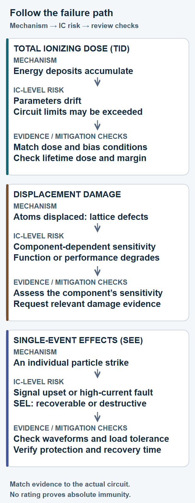
TID accumulates as ionizing radiation deposits energy. Electrical parameters can drift until the circuit no longer meets its requirements. A dose in krad(Si) means thousands of rad of absorbed dose in silicon; the material designation matters (absorbed-dose units).
Displacement damage creates defects in the semiconductor lattice as particles displace atoms. It is cumulative, but sensitivity depends on the component and its function. Treat it as a separate assessment rather than assuming that a TID rating covers it.
SEE arise from individual particle strikes. A single-event transient (SET) is a temporary signal disturbance; a single-event upset can change a stored state. Single-event latchup (SEL) creates a persistent high-current path. It may be recoverable if protection removes power in time, or destructive if the current causes damage. ECSS also warns that protected latchup can leave damage that reduces long-term reliability, even without outright failure. Burnout and gate rupture are other potentially destructive modes.
TI’s LDO test report explains why latchup can persist until power is removed or the device is destroyed. A TID result cannot establish SEE response: cumulative drift and individual-strike behavior require different evidence.
Mitigations work at different levels
TI’s handbook overview names hardening by process and design, including layout techniques, redundancy and error correction. This is an overview, not the detailed handbook.
The ESA microelectronics page describes a mitigation handbook covering manufacturing processes, layouts, analog and digital circuits, software and the immediate electronic system. Its techniques are guidance, not requirements. The following table is our practical grouping.
| Level | What it changes | What to check |
|---|---|---|
| Process | Semiconductor technology | Evidence for the technology actually delivered |
| Layout | Device geometry and surroundings | Validation on the implemented design |
| Circuit | A block’s response to faults | Which signals and failure paths it covers |
| System | Detection, isolation and recovery | Whether action arrives before damage or lost service |
The JSC radiation-assurance overview describes an iterative process with hardware, software and operational mitigation, and identification of residual risk. The engineering task is to connect these levels to a specific failure consequence.
Analog and power parts need different questions
Error correction and voting can protect digital states. A transient on a regulator output or converter input is different: downstream circuits may accept the disturbed analog signal as valid. Our engineering inference is that digital redundancy alone does not reduce that excursion. The signal path needs its own tolerance and recovery checks.
LET means linear energy transfer: deposited energy per path length normalized to material density, expressed here in MeV cm²/mg (NEPP testing primer, slide 22).
TI’s report on the TPS7H1101A-SP regulator provides a useful example. Table 5 records no observed SEL at an effective LET of 85 MeV cm²/mg and a die temperature of 125 °C, with the stated supply and load conditions. TI calculates effective LET at the silicon after accounting for the beam’s path through intervening material.
That result is a vendor observation under specified exposure conditions, not an absolute immunity claim. The report also characterizes output transients by deviation, cross section and recovery time. It describes both fast output disturbances and a soft-start event that initiated a restart.
For the power team, the next question is whether the load can tolerate those waveform shapes at its operating voltage and current. A restart that recovers the regulator can still interrupt the telemetry board. Compare the report’s setup with the actual circuit before carrying its results into a design review.
Pair telemetry with a protection response
TI’s satellite telemetry brief discusses monitoring rail voltages, currents and temperatures. Current sensing can reveal undercurrent or overcurrent conditions that may suggest latchup or other hazards. The brief also notes that fault-critical applications may need increased measurement bandwidth.
Our engineering inference is that detection must be paired with a response budget: sensing, decision and power isolation all take time. A sampled health-monitoring channel should not automatically be treated as fast latchup protection. Verify the complete path and consider what happens if that path is itself disturbed.
Compare product grades using part-specific evidence
The same brief compares the ADC128S102QML-SP and ADC128S102-SEP. TI states that they share analog parametric performance and functional features, while reporting these radiation ratings:
| Device | TID rating | SEL rating |
|---|---|---|
| ADC128S102QML-SP | 100 krad(Si) | 120 MeV cm²/mg |
| ADC128S102-SEP | 30 krad(Si) | 43 MeV cm²/mg |
TI positions the plastic SEP version for low Earth orbit and the ceramic QML version for geosynchronous orbit. These are vendor product positions, not a general orbit-to-package rule. The brief does not supply the underlying radiation test conditions. Package type alone cannot establish suitability for a mission.
Turn radiation evidence into a selection plan
ECSS makes the assurance program project-specific. Its radiation design lifetime is the lifetime under the specified radiation environment; the calculated dose at its end is part of the margin assessment.
Take these questions to the design review:
- What environment, shielding and radiation design lifetime are assumed?
- Which original reports match the delivered part, revision and lot?
- Are bias, load, temperature and failure criteria relevant to this circuit?
- How do the tested LET range, exposure conditions and die temperature relate to the assessed mission environment?
- What analog error and interruption can each downstream load tolerate?
- How will faults be detected, isolated and recovered, and who accepts residual risk?
The useful outcome is a traceable selection decision: a part, its evidence, the circuit’s tolerance and a recovery plan. A label helps organize that discussion; it does not finish it.
Selected primary sources
- ECSS radiation hardness assurance standard — Effect families, mission lifetime and radiation-assurance requirements.
- TI TPS7H1101A-SP radiation report — Device-specific latchup and transient results under stated test conditions.
- TI satellite telemetry brief — Rail monitoring and the ADC product-grade rating comparison.
- ESA microelectronics development methodology — Mitigation guidance across process, circuit and system levels.
- NASA JSC flight-computing overview — The iterative radiation-assurance and residual-risk framework.
- NASA NEPP radiation-testing primer — LET terminology; see slide 22.
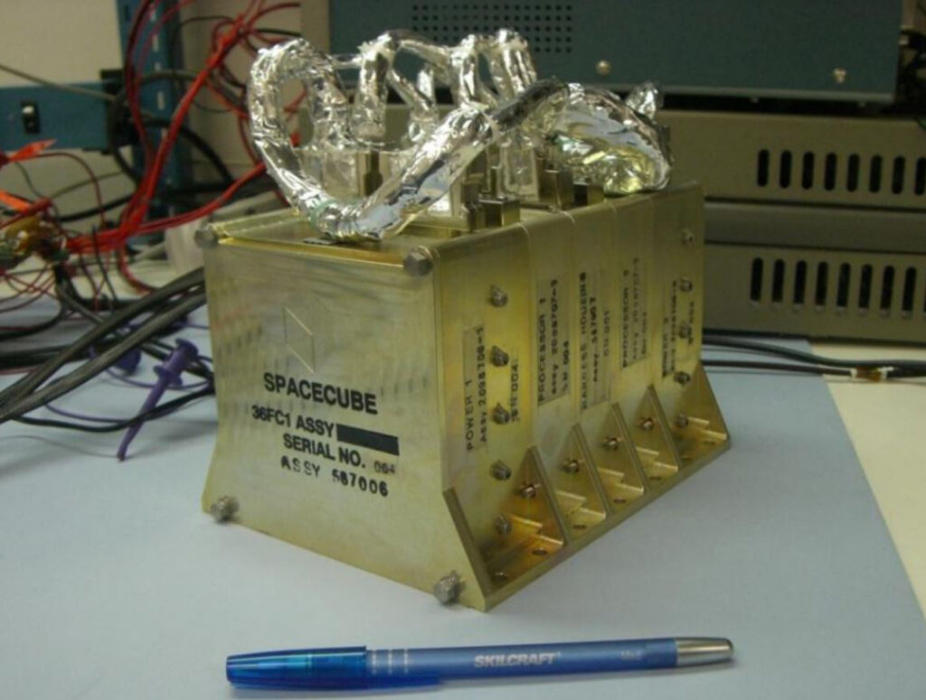
- NASA SpaceCube technology overview — SpaceCube’s radiation-tolerant FPGA and upset-detection/correction design strategy.
Related Insights
- One Isolation Barrier, Four Different Gate-Drive Problems — A related selection framework connecting device conditions, protection and measured evidence.
- Why High-Voltage ICs Move to Ceramic Packages — Adjacent context on package choices, thermal demands and qualification; not radiation qualification.
Featured photo: NASA Goddard’s SpaceCube processing unit. NASA describes the architecture as combining commercial radiation-tolerant FPGAs with upset detection and correction. Credit: NASA/Goddard. Image and architecture source. NASA does not endorse this article or the products mentioned.
Informational engineering analysis, not mission qualification or vendor endorsement.
Please link to this article when sharing. Contact us for permission to republish the full article.