Consider a hypothetical radio frequency (RF) module with an amplifier chip, filters and a sealed lid. Its ceramic package must carry fast signals, remove heat and protect the devices inside. Choosing a ceramic platform starts with those requirements.
HTCC (high-temperature co-fired ceramic) and LTCC (low-temperature co-fired ceramic) describe co-firing families. For HTCC vs LTCC selection, compare the documented ceramic, conductors, geometry and assembly against the electrical path, heat path and enclosure requirements. Request evidence for each before selecting a stack.
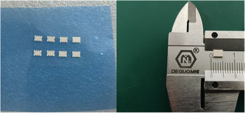
Photo: LTCC (low-temperature co-fired ceramic) filter research prototypes from Bai et al., Micromachines 17, 1173, Figure 8, published 9 October 2026, Creative Commons Attribution (CC BY). Reproduced unchanged. Exact capture date and fabricator are not reported. The photo shows filter components rather than a custom package.
1. Start with requirements, then compare ceramic and conductor
Both platforms use co-firing: ceramic layers and their embedded conductors are fired together. Thin unfired sheets are formed by tape casting (casting a ceramic slurry into a thin sheet), vias (interlayer conductive connections) are punched and filled with metal paste, and metallization (metal patterns) is printed on each layer. The stack is pressed and fired so that sintering (heat densification) turns it into one solid body. Kyocera’s multilayer package process then adds plating and brazing (joining with a melted filler metal while the parts stay solid) of metal parts.
Alumina is aluminum oxide; AlN (aluminum nitride) is a different ceramic. Glass ceramic denotes a glass/ceramic material system; its composition must be specified. Kyocera describes its LTCC as alumina combined with glass, which allows lower-temperature firing and low-resistance copper or silver conductors.
| Criterion | HTCC | LTCC |
|---|---|---|
| Ceramic body | Alumina; some suppliers also list AlN | Glass-ceramic systems; Kyocera’s examples combine alumina with glass |
| Conductor metal | Refractory metal such as tungsten (W), as in supplier HTCC routing listings | Lower-resistance copper (Cu), silver (Ag) or gold (Au), depending on supplier system |
| Firing | Higher temperature, with supplier-defined atmosphere and schedule | Lower temperature; schedule and atmosphere depend on tape and paste |
| Closure and joining | Braze-compatible seal rings (metal frames on the ceramic that lids join) and metal parts listed by suppliers | Varies by grade; some copper grades have documented limits |
| Main caution | Tungsten conductor loss at high frequency in modeled comparisons | Dielectric loss and thermal expansion differ widely between grades |
For supplier-specific examples, NEOTech lists alumina and AlN HTCC, plus gold, silver and mixed-metal LTCC systems. Read the table as a list of questions, not a verdict. Conductor system and grade vary by supplier, and firing temperature describes how a part is made, not how hot it may run in service.
2. Electrical and thermal paths
RF performance depends on the dielectric constant (how much electric energy a material stores relative to vacuum), the loss tangent (a measure of dielectric loss), conductor loss, geometry and transitions (changes between interconnect structures, such as a via or a package launch). The family label settles none of these. Within one supplier’s LTCC grade list, the representative loss tangent at 2 gigahertz (GHz, two billion cycles per second) differs by more than three times, and CTE (coefficient of thermal expansion, relative change in length per degree of temperature) differs too, with different die-side and board-side matching priorities. These are material values, not finished-circuit results, and should not be extended to millimeter-wave frequencies (roughly 30 to 300 GHz, corresponding to free-space wavelengths of approximately 1 to 10 millimeters).
A Kyocera-authored paper, with no established publication date, models selected material and geometry pairs at 10 GHz. In those models a gold LTCC conductor shows lower conductor loss than a tungsten HTCC conductor, but a medium-loss LTCC dielectric can push combined loss above alumina as line width grows. The results are modeled, not measured, and transitions are excluded. Use the paper as a reason to request stack-specific models and measured test structures, not as a ranking.
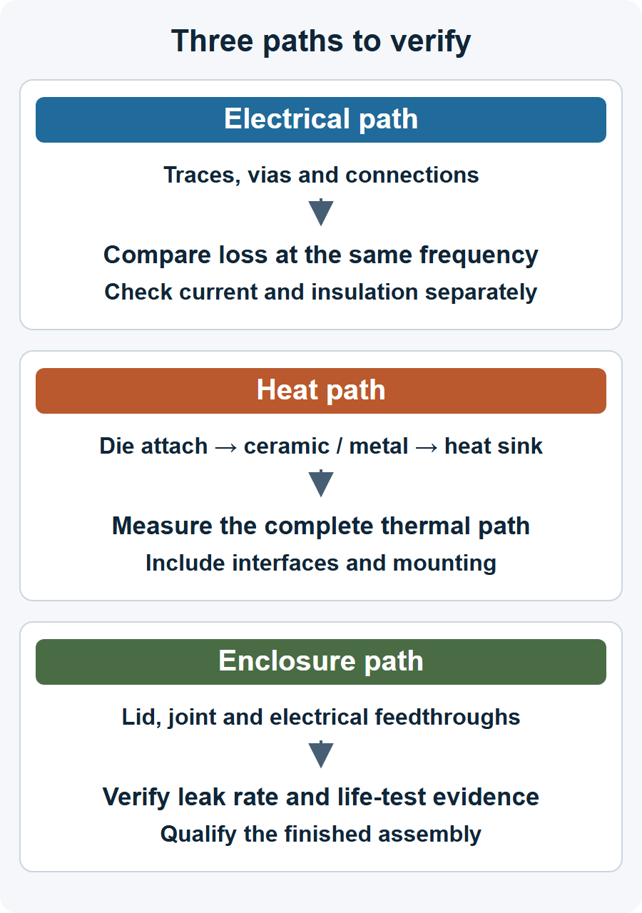
Heat has its own path. Thermal conductivity is a material property, but chip temperature depends on the whole route: the die attach (the joint that secures the chip), ceramic thickness, thermal vias, heat-spreading metal, interfaces and the cooling boundary. Evaluate that route together; a co-firing label names no thermal winner. Signals and power also cross the enclosure wall through feedthroughs (electrical connections through the enclosure boundary), which the next section covers.
3. Lid, seal, feedthrough and life
A ceramic body alone does not make a hermetic part; the finished assembly does: the lid (the cover that closes the cavity), a seal ring (a metal frame on the ceramic that the lid joins), feedthroughs, the joining process and the test. Kyocera’s North American page lists braze-compatible seal rings for alumina HTCC and some LTCC, with an exception for copper LTCC, and its Japanese page marks dissimilar-material joining as unavailable for its three copper grades. These pages do not establish a brazed closure route for those copper grades; confirm the actual process for your grade.
Seam welding closes many metal lids. AMADA WELD TECH describes parallel seam sealing as resistance joining of a metal lid to a metal package, or to a metal seal ring on a ceramic package: two rotating wheel electrodes follow the perimeter, and current plus force creates overlapping welds. That describes the process, not compatibility with a particular ceramic stack or an achieved leak rate. Ask for leak evidence on the finished part: fine-leak and gross-leak methods (checks for small and large leaks), the tracer gas (a detectable gas used to find leaks) and the acceptance limit.
Life is a separate question. Thermal cycling, humidity, metallization adhesion and via continuity should be shown on your stack and mission profile (expected service stresses and lifetime). High-voltage isolation needs sustained working voltage, specified test voltage, spacing, dielectric thickness and partial-discharge limits (limits on localized discharges that do not bridge the full insulation). Current needs conductor and via limits and measured temperature rise. HTCC does not guarantee any of these, and LTCC does not rule them out.
4. Production roles, with supporting China context
A ceramic package involves body fabrication, metal-part brazing and plating, assembly and lid sealing, and test and qualification. One company page rarely covers all four. Also separate a custom package (a body designed around your chip) from a finished component (a catalog part with a fixed function).
Public company pages in China show different roles. Hebei Sinopack, in Shijiazhuang, describes alumina and AlN multilayer package processes: tape casting, punching, printing, lamination (pressing stacked layers together), sintering, plating and brazing. Shanghai Xintao Micro New Materials lists HTCC substrates and packages with tungsten routing and joining options including seam welding, on an undated page. Sunlord, in Shenzhen, publishes a datasheet, revised 6 May 2026, for a surface-mount LTCC low-pass filter (a part that passes low frequencies) aimed at mobile communication and base stations.
These are company statements of role. They do not show that a custom LTCC package can be fabricated in China, nor capacity, qualification, price or buyer access. The Sunlord filter is a finished component, not a package service, and the same distinction applies to the featured photograph.
5. Five questions for your next step
These questions apply to any supplier in any region.
- Which exact ceramic, conductor and finish does the quote assume, and what firing schedule and atmosphere were qualified?
- Which models or measurements cover my frequency band, trace geometry, transitions and temperature range?
- How is the heat path modeled and measured with my die attach and cooling boundary?
- Which lid, seal, feedthrough and leak-test method and limit apply, and what post-stress results exist?
- Who owns fabrication, sealing and test, and what are the nominal shrinkage, compensation and finished-feature tolerances by axis, NRE (non-recurring engineering, one-time design and tooling cost), yield and lead time?
Before sending them, write your requirements table: band, power, voltage, current, cavity size, environment and volume. For related background, see the Insights on RF module packaging options and heat and isolation in ceramic packages for high-voltage integrated circuits (ICs).
6. Primary sources
- Kyocera, what LTCC substrates and packages are: material definition, grade properties, joining notes.
- NEOTech, ceramic substrate platforms: supplier-specific alumina/AlN HTCC and LTCC conductor systems.
- Kyocera North America, ceramic packaging materials: seal-ring joining statements.
- Kyocera authors, ceramic transmit/receive module material selection: modeled RF comparison.
- AMADA WELD TECH, parallel seam sealers: seam-welding process.
- Hebei Sinopack, company profile.
- Shanghai Xintao Micro New Materials, HTCC substrate and package listing.
- Sunlord, SLFL series datasheet, revised 6 May 2026.
Please link to this article when sharing. Contact us for permission to republish the full article.