
An inverter is often described as a bridge of power switches. That is true but incomplete. The useful question for inverter control ICs is not which switch is used in isolation. It is which control, sensing, protection, bias and communications functions make the bridge behave predictably when it drives a motor, exchanges energy with the grid, runs from a battery or supports a critical load.
This matters because solar photovoltaic (PV), energy-storage systems (ESS), industrial drives, electric-vehicle traction and uninterruptible power supplies (UPS) all use inverter functions, but not the same energy path or qualification envelope. A grid-tied inverter regulates current against the grid. A motor inverter shapes phase currents and torque. A traction inverter must operate within a vehicle high-voltage, environmental and functional-safety architecture. A UPS controls AC output for a critical load.
Market pull is real; the IC market is not one number
The deployment backdrop is substantial. The International Energy Agency reports that nearly 700 GW of renewable capacity was added in 2024, nearly 80% of it solar PV. It expects 2025 solar investment of USD 450 billion and power-sector battery-storage spending of USD 66 billion. Those are equipment and infrastructure figures, not inverter-IC revenue or an IC total-addressable market. IEA: Global Energy Review 2025 and World Energy Investment 2025 provide the context.
For IC suppliers, the better screen is: which interface becomes difficult in a defined inverter, and can an IC reduce that difficulty without simply moving it to the module, magnetics, firmware or cooling system?
The power path is simple. The control plane is not.
At a high level, an inverter converts a DC source or DC link into controlled AC. The power path contains the DC link, bridge, output filter where required, passives, magnetics, cooling and mechanical insulation. Those are not automatically IC sockets.
The IC opportunity sits around that energy path. A public 10 kW hybrid-inverter reference design from Texas Instruments, for example, combines PV inputs, a battery port, bidirectional conversion, a grid-connected DC/AC stage and one real-time controller across three power stages. It illustrates a possible partition, not a universal topology. TI TIDA-010938
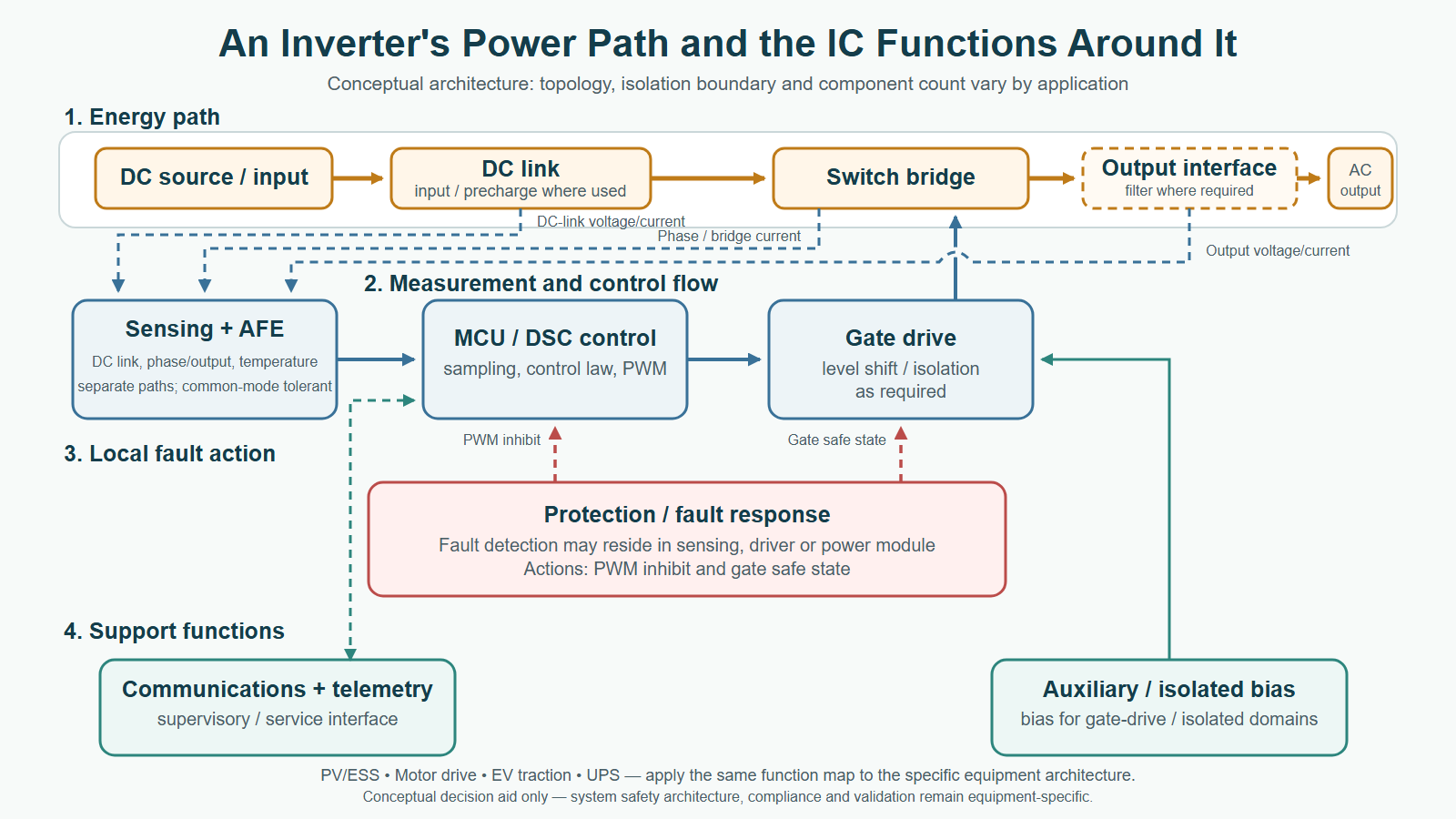
Six functions that surround the bridge
| IC function | Its job at the physical boundary | What makes it application-specific |
|---|---|---|
| Real-time controller | Samples feedback, runs the control law and creates pulse-width-modulation (PWM) commands. | Motor field-oriented control, grid synchronization, regulated UPS output and traction torque control demand different software, timing and diagnostic partitions. |
| Gate driver | Translates a low-voltage control command into a switch-gate command. It can also provide level shifting, isolation, undervoltage lockout or fault behavior. | Gate charge, switching edge rate, the power module, the high-side reference and the required fault response determine the actual driver requirement. |
| Current, voltage and temperature sensing | Closes a control loop and informs diagnostics. | A shunt, Hall or magnetic sensor, isolated modulator and divider/ADC chain solve different bandwidth, accuracy, loss and common-mode problems. |
| Local hardware protection | Detects a condition that requires action before firmware or fleet telemetry can react. | The location of the fault, its energy and false-trip immunity matter more than a generic “smart” label. |
| Auxiliary and isolated bias | Powers floating gate-drive and sensing domains, and influences start-up and fault recovery. | Rail sequencing, isolation, negative bias needs, standby loss and electromagnetic coupling all depend on the selected power stage. |
| Communications and telemetry | Connects the inverter to service, supervisory or energy-management functions. | The field protocol, cable environment, isolation boundary and diagnostic ownership differ between PV/ESS, vehicles, industrial equipment and UPS fleets. |
An MCU or digital signal controller (DSC) may run the control algorithm; that does not make it a substitute for an analog front end (AFE), comparator, isolator, gate driver or autonomous protection path. Likewise, an isolation rating on one IC is not proof that the complete inverter meets its insulation, surge, electromagnetic-compatibility or safety obligations.
What changes by inverter application
| Equipment | Energy/load context | Where power-analog ICs earn attention |
|---|---|---|
| PV and ESS power-conversion system (PCS) | Grid-synchronous AC current; ESS may charge and discharge through bidirectional stages. | Grid/bus sensing, gate drive, isolation, auxiliary power and supervisory communications. Infineon BESS application map |
| Industrial motor drive | PWM-controlled current into an inductive motor; speed and torque are the controlled result. | Phase-current feedback, driver timing and protection, low-noise analog acquisition and control timing. TI 200-480 VAC drive reference design |
| EV traction inverter | Battery DC to three-phase motor currents, with regenerative energy returning to the DC bus when vehicle control and battery-acceptance conditions permit. | Isolated gate drive and bias, phase/DC-bus sensing, thermal feedback and fault shut-down. TI traction-inverter discussion |
| UPS | A regulated AC output supplies a critical load; rectifier, charger, battery and bypass functions may be present. | Output sensing, PWM control, gate drive, auxiliary rails and bus monitoring. TI DC/AC inverter reference design |
These rows are starting points, not bills of materials. An isolated driver may be appropriate in one leg and not another. A fast comparator path may complement, rather than replace, precision measurement for control. The exact topology and standards allocation belong to the equipment program.
The hard interfaces are where opportunity concentrates
ChinaSemiOps engineering inference: a plausible power-analog IC opportunity is created by a hard interface, not merely by the word “inverter.” The useful questions are whether a floating switch reference, fast common-mode transient, noisy current measurement, DC-link fault, auxiliary-bias domain or service network creates a measurable integration problem.
That is why the most credible concepts are usually bounded: a current-feedback chain that survives a specified PWM environment; a protected gate-drive companion around a known module; an isolated-bias and fault-monitoring function with clear start-up behavior; or a controller-adjacent AFE that improves a defined control loop. The switch, power module, magnetics, cold plate and final system qualification remain separate responsibilities.
This article deliberately does not choose a universal winner among silicon MOSFETs, IGBTs, silicon carbide or gallium nitride. Switching-device choice depends on voltage, frequency, topology, loss, electromagnetic interference, thermal design, cost and validation envelope. A reference design or evaluation board shows a possible implementation, not mass deployment or market leadership.
Players compete by function, not by one “inverter IC” category
- Texas Instruments publishes C2000 controller, sensing, isolated gate-drive and reference-design material across solar/ESS, motor drives and traction examples.
- Infineon maps gate drivers, MCUs, current sensors, auxiliary power, isolation and connectivity to hybrid-inverter and BESS functions.
- Analog Devices documents isolation-centric inverter signal chains for industrial motors and grid-tied PV, including current-feedback and gate-drive boundaries.
- NXP maps MCU/DSC, isolated driver, auxiliary switch-mode-power control and connectivity across several PV inverter forms.
- STMicroelectronics demonstrates a more integrated, low-voltage three-phase motor-drive approach in its STDRIVE102 family, combining driver, sensing AFE and over-current detection. That does not make the part a PV, utility-storage or traction-inverter substitute.
These are attributable portfolio examples, not share rankings or evidence of a design win. For a dedicated isolation comparison, see One Isolation Barrier, Four Different Gate-Drive Problems. For a higher-voltage conversion-system discussion, see Solid-State Transformer Power IC Opportunities.
A five-question screen before proposing an IC
- What energy path and load are we serving? Grid, motor, regulated AC load or a bidirectional battery path are materially different.
- Which domains move together? Map the DC-link voltage, floating high-side references, measurement points and required isolation boundary.
- Which fault needs local action? Separate a deterministic hardware response from reporting, logging and firmware recovery.
- Which measurement must survive PWM noise? Define bandwidth, accuracy, common-mode environment, synchronization and overload behavior before choosing the sensing architecture.
- Who owns the evidence? The inverter maker, module supplier, firmware team and compliance owner must allocate qualification, safety, thermal, electromagnetic and service validation.
The result is more useful than a generic inverter-market forecast: it identifies the control-plane boundary that an IC can credibly improve. Map one named equipment architecture first; only then decide whether the answer is a discrete IC, a companion function, a module feature or no new silicon at all.
Engineering and safety boundary: this is a public-source educational framework, not a component recommendation, a production design, or safety/compliance advice. Isolation, protection, thermal, layout, electromagnetic compatibility and applicable standards require system-specific analysis and validation.