
The next EV on-board charger (OBC) improvement is unlikely to come from swapping one transistor for another. Public reference designs increasingly combine bidirectional power flow, fast SiC or GaN switches, real-time control and a tighter thermal/isolation design. The engineering prize is a smaller, more efficient and more capable conversion system—but only when the whole energy path is designed together.
For semiconductor teams, that changes the question. Instead of asking “which switch wins?”, start with the grid connection, battery voltage, required direction of power flow, cooling envelope and safety boundary. Those choices decide which power device, gate drive, sensing and control functions actually matter.
Three takeaways
- Bidirectionality is an architecture choice, not a switch feature. It affects both the AC front end and the isolated DC/DC stage.
- SiC and GaN solve different versions of the same density problem. Voltage class, topology, switching frequency, layout and qualification decide the fit.
- The strongest IC opportunity is usually around the power switch. Protection, isolated bias, current/voltage sensing, timing and measured validation become more valuable as switching speed and power rise.
Start with the energy path
An OBC accepts AC from the grid and charges the high-voltage battery. A common functional path is AC input → power-factor-correction (PFC) or active front end → DC link → isolated DC/DC converter → battery. In the widely documented two-stage architectures, the isolated converter preserves the grid-to-battery electrical boundary; the exact boundary and required test evidence depend on the topology and applicable rules.
In a bidirectional OBC, that path must also work in reverse under the intended operating conditions. This is why a bidirectional front end and a symmetric resonant DC/DC stage often appear together in public reference designs. TI’s 6.6 kW GaN reference uses two-phase totem-pole PFC plus a full-bridge CLLLC converter; Wolfspeed’s 6.6 kW SiC reference uses a bidirectional totem-pole PFC plus CLLC. These are useful engineering examples, not evidence that every vehicle uses the same topology. The OBC rating is an upper bound on AC charging: EVSE/grid supply, battery acceptance, state of charge and temperature can still limit it. DC fast charging follows an external DC path and does not use the vehicle OBC’s main power-conversion stage. TI reference design · Wolfspeed reference design
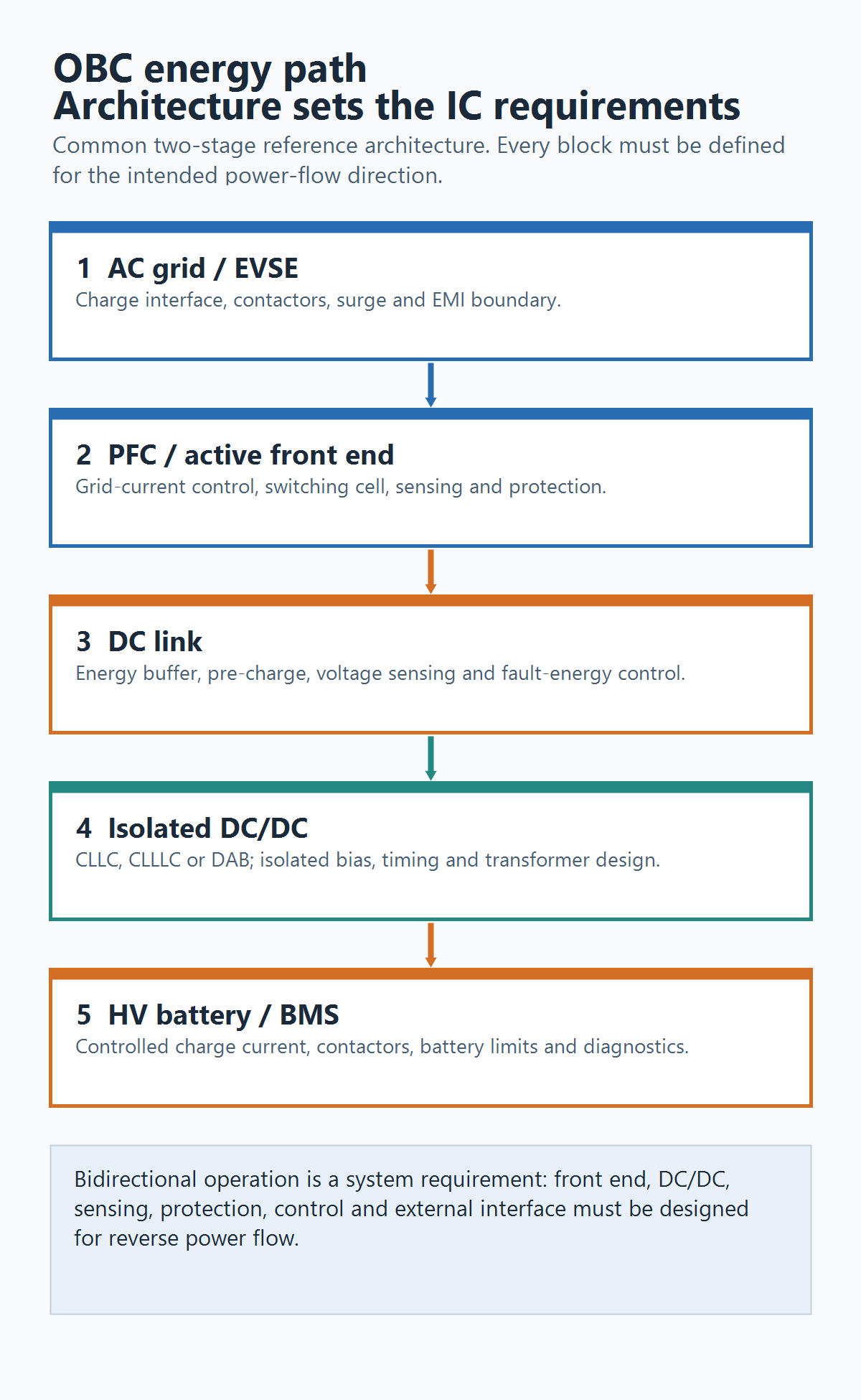
The recurring decision questions are:
- At the AC input/PFC stage: switch voltage/loss, grid-current sensing, control-loop bandwidth, EMI and grid-interface protection.
- At the DC link: energy buffering, pre-charge, voltage sensing, surge/fault handling and layout.
- At the isolated DC/DC stage: gate timing, isolated bias, synchronous-rectification sensing, transformer design and insulation coordination.
- At the battery interface: accurate current measurement, protection ownership, BMS communication and safe-state behavior.
What has materially improved
1. Bidirectional hardware has released-reference and limited deployment evidence
The direction of travel is visible in several public reference platforms. TI documents 6.6 kW and 7.4 kW-class GaN-based bidirectional OBC work. Wolfspeed documents a 6.6 kW SiC platform with charging and inversion modes. Infineon documents an 11 kW, approximately 800 V DC-side bidirectional AC/DC reference that operates from three-phase input, or 7.3 kW from single-phase input. TI’s 7.4 kW guide · Infineon’s 11 kW AC/DC application note
That does not prove vehicle-level V2G or V2H deployment. It does show that reversible energy flow is a concrete design requirement engineers can prototype with public hardware and controls. Renault also identifies its Renault 5 E-Tech Electric as using an 11 kW bidirectional AC charger, with market-specific V2G service in France; that is useful named deployment evidence, not a global adoption measure. Renault product/service release The practical implication is simple: choose the PFC/front-end and isolated DC/DC topology as a pair, then define the needed grid-interface and battery-side protections before comparing devices.
2. Wide-bandgap devices are enabling higher-frequency trade-offs—not removing trade-offs
SiC and GaN can reduce switching loss or support faster switching in the appropriate operating window. That can allow smaller magnetics and filters, which helps vehicle packaging. In its published 6.6 kW references, TI reports 96.5% peak efficiency and 3.8 kW/L for an open-frame GaN design; Wolfspeed reports 96.5% peak efficiency and 3 kW/L for a SiC design. Those are supplier-specific, open-reference results—not a fair SiC-versus-GaN scorecard. TI · Wolfspeed
The trade-off shifts instead of disappearing. Faster edges make gate-loop inductance, common-mode current, electromagnetic interference and protection timing more consequential. A high-voltage SiC stage often makes short-circuit response, controlled turn-off and isolated-bias behavior central. A fast GaN stage can place even more weight on gate window, dead time, barrier placement and local layout. The right device choice is therefore stage-specific.
3. Higher power is bringing the rest of the power stack into the design decision
Public OBC work now spans 6.6–7.4 kW single-phase examples and 11 kW three-phase examples. ST’s 11 kW bidirectional reference combines three-phase two-level PFC with isolated DC/DC. onsemi’s OBC portfolio also presents a 11 kW matrix-converter demonstration; its passive-component reduction statement should be treated as a vendor claim until it is verified against the exact system. ST reference brief · onsemi OBC page
At these power levels, no switch is evaluated alone. Heat removal, magnetics, creepage and clearance, current sensing, EMI filters, gate-drive placement, auxiliary power and fault shutdown all set the usable system margin. Vendor block diagrams make this visible: alongside power devices sit isolated gate drivers, amplifiers/comparators, controllers, auxiliary supplies and vehicle communication interfaces. onsemi 11 kW OBC solution map
4. Single-stage and integrated boxes are real directions, not default answers
TI now publishes an 11 kW three-phase, bidirectional single-stage series-resonant DAB reference. That demonstrates a credible alternative to the better-established two-stage PFC plus isolated DC/DC path. It does not mean “single-stage” removes all filtering, energy storage, isolation or qualification work; those functions simply have to be accounted for within the chosen boundary. TI 11 kW single-stage reference
At the vehicle level, OBC and high-voltage-to-low-voltage DC/DC functions are also being combined into shared power boxes. Valeo lists 7, 11 and 22 kW OBC options in an OBC/DC-DC combo offering. That is a product-direction signal, not proof that integration lowers cost or raises reliability for every vehicle program. Valeo OBC/DC-DC combo
Where the semiconductor opportunity actually sits
The tempting thesis is “OBC growth means more high-voltage switches.” That is true but incomplete, and it is rarely distinctive. The more useful opportunity map is the set of functions that make a fast, isolated power stage repeatable:
- Protected isolated gate drive: correct turn-on/off behavior, fault reporting and controlled shutdown under the exact switch and topology constraints.
- Isolated bias and supervision: startup behavior, undervoltage lockout, bias regulation and monitoring across floating domains.
- Current and voltage measurement: low-latency, well-characterized feedback for control and protection—especially around PFC and resonant-tank currents.
- Real-time control and communication: PWM timing, analog conversion, fault reaction and vehicle-network integration.
- Power-package and layout evidence: not merely an IC package rating, but measured switching, thermal and isolation performance in the intended module and cooling arrangement.
This is consistent with our earlier isolated gate-driver technology analysis: peak drive current and a headline isolation rating are screening numbers, not a complete selection method. For an OBC, switch, topology, working voltage, bias architecture, measured dv/dt, physical spacing and fault tests need to be defined together.
A practical review checklist
Before selecting a device or proposing a custom IC, write down:
- Grid phase and input-voltage range; battery voltage and charge/discharge direction.
- Power level, cooling boundary and packaging target.
- PFC/active-front-end and isolated-DC/DC topology, including the isolation boundary.
- Switch technology and its actual gate, short-circuit and switching constraints.
- Required current/voltage measurements, protection reaction time and safe-state behavior.
- The evidence plan: corner conditions, thermal limits, conducted/radiated EMI, isolation, fault testing and end-equipment compliance.
The result is a decision that an engineering team can test. It avoids treating a supplier demonstration, a transistor figure of merit or a vehicle-charging headline as proof that a particular OBC architecture is ready for a program.
The decision for OBC technology planning
OBC technology is improving through system co-design: reversible energy paths, faster switches, more capable control and a denser thermal/mechanical implementation. That makes the category relevant to power-semiconductor and analog-IC teams—but the best work starts with a bounded system envelope rather than a generic OBC market claim.
Use a source-backed semiconductor-function map to define topology, voltage, power flow and validation conditions before creating a component shortlist or considering custom silicon.
Selected primary sources
- TI PMP22650: GaN-based 6.6 kW bidirectional OBC — topology, control approach and vendor-reported reference metrics.
- TI 7.4 kW bidirectional OBC guide — common OBC functional path and CLLLC implementation context.
- Infineon 11 kW bidirectional AC/DC application note — 800 V-side, single-/three-phase AC/DC reference evidence.
- Wolfspeed 6.6 kW bidirectional SiC OBC reference — CCM totem-pole PFC, CLLC and listed reference specifications.
- ST 11 kW bidirectional charger reference — three-phase PFC plus isolated DC/DC reference architecture.
- onsemi OBC solution page — matrix-converter demonstration and system-component context.
Disclosure: This is a public-source engineering overview, not a vehicle-program design, safety, compliance or component-qualification recommendation. Verify the current datasheet, exact topology, layout, thermal path and end-equipment requirements before making a design decision.