Featured photograph: A smartwatch and companion phone illustrate connected wearable use; the photograph does not identify the sensing ICs inside. Photo: Amanz on Unsplash (Unsplash License).
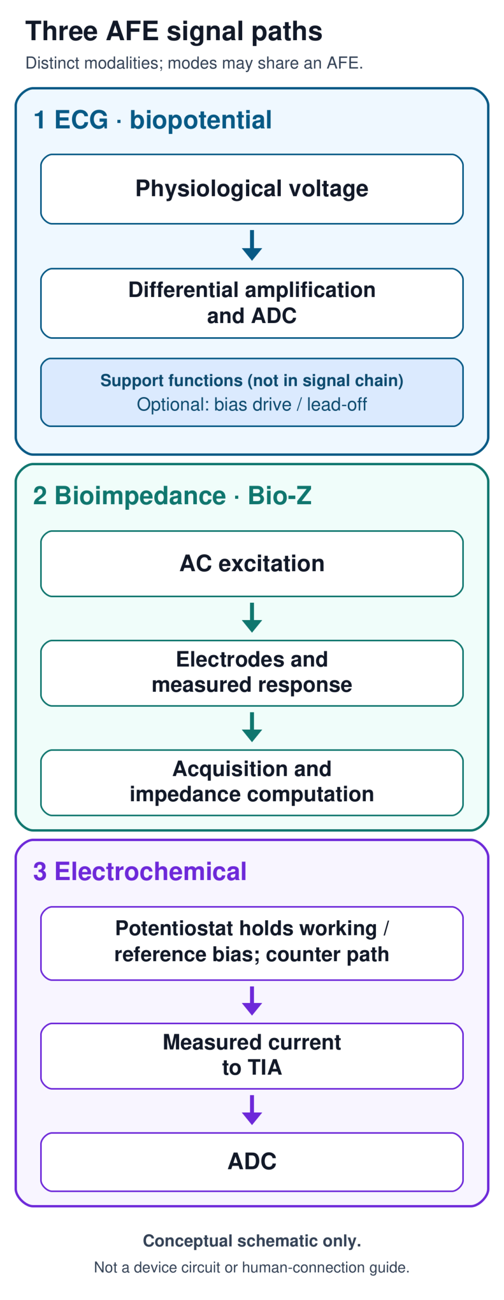
Choosing a biosensing analog front end (AFE) starts with one question: what electrical quantity does the sensor hand you, and does the measurement need you to drive something first? An electrocardiogram (ECG) electrode pair delivers a voltage the body already produces. A bioimpedance measurement applies an AC signal and reads the response. An electrochemical cell holds a controlled bias and reads a current. In each case the AFE conditions the signal for the analog-to-digital converter (ADC), the block that turns the analog level into digital numbers.
Those are three different signal paths. They do not automatically mean three different chips: some AFEs integrate more than one mode, and some designs split modes across devices. This article gives a way to match the path to the silicon, and a checklist to carry into a design review.
Three measurement paths, one question
The unifying idea is simple: identify what is sensed, what must be driven, and what the ADC ultimately sees.
Biopotential (ECG, and electroencephalography, EEG). The signal is an endogenous voltage: the body generates it, and the measurement adds no excitation. Separately from that signal origin, a design may add active support circuitry. The ADS1292R lists a right-leg-drive amplifier and the ADS1299 a bias-drive amplifier; both provide configurable lead-off detection and programmable-gain amplifiers (PGAs) ahead of 24-bit converters (ADS1292R, ADS1299). Bias drive and lead-off detection are configurable options, not requirements of every design, and they do not change where the signal comes from.
Bioimpedance (Bio-Z). The AFE applies AC excitation and measures the response. In ADI’s AN-1557 two-wire example, current passes through a transimpedance amplifier (TIA), voltage and current are measured, and a discrete Fourier transform (DFT) extracts the impedance (AN-1557).
Electrochemical sensing. A typical three-electrode cell uses working, reference and counter electrodes. A potentiostat holds the working-to-reference bias while current flows through the counter path, and a TIA converts the measured current to a voltage (AN-1563).
Comparison: what each path asks of the AFE
| Dimension | Biopotential (ECG/EEG) | Bioimpedance | Electrochemical |
|---|---|---|---|
| Signal origin | Endogenous differential voltage | Response to applied AC excitation | Current in an electrochemical cell |
| Excitation or bias | None for the measurement; common-mode bias and lead-off functions optional as configured | AC excitation | Working-to-reference bias held by the potentiostat; current returns through the counter path |
| Readout concept | Differential PGA, then ADC | Measure the response and compute impedance. AD5940/AN-1557: TIA and DFT. ADS1292R respiration: modulation and demodulation on channel 1 | In the AN-1563 topology, a TIA converts working-electrode current to voltage |
| Source-backed examples | ADS1292R, ADS1299 | AD5940; ADS1292R respiration mode | AD5940; AN-1563 topology |
| Boundary | ADC bit count is not physiological accuracy | Excitation and processing depend on configuration | A front end is not a complete sensor or device |
Sources: ADS1292R, ADS1299, AD5940, AN-1563, AN-1557, ADS1292R datasheet.
One chip, several modes: what the sources show
ADI describes the AD5940 as an impedance and electrochemical AFE with excitation DACs, a potentiostat, TIAs, a switch matrix, an ADC and impedance-processing functions. Its product page lists electrochemical measurement, skin and body impedance, and continuous glucose monitoring among applications (AD5940). That is a statement about electrical capability. It is not evidence of a glucose-specific sensor design, a complete approved device or clinical accuracy.
ADI’s AN-1557 goes further, pairing the AD5940 with an AD8233 ECG AFE so ECG, body impedance and electrodermal measurement can share electrodes (AN-1557). Note the source-specific restriction attached to that example: the note prohibits connecting its evaluation board to a human. The reference hardware is built around a simulator test board, and it includes isolation and current-limiting components. Treat it as bench-development material.
Integration also has costs. The ADS1292R datasheet’s ECG-with-respiration example places respiration on channel 1 and ECG on channel 2, and the two can run together. Channel 1, once respiration mode is enabled, cannot also acquire ECG, and that example diagram omits patient and input protection (datasheet). When you evaluate a multi-mode part, check which modes it can run concurrently and which share resources.
Vendor numbers: read them with their conditions
TI lists the ADS1292R at 335 µW per channel and 8 µV peak-to-peak input noise at 150 Hz bandwidth and gain 6 (ADS1292R). TI lists the ADS1299 at 1 µV peak-to-peak input noise at 70 Hz bandwidth (ADS1299). Both are manufacturer specifications under their stated conditions.
The bandwidths differ, so the two noise figures are not a like-for-like ranking, and this article does not rank the parts. Likewise, a 24-bit ADC describes quantization resolution, not physiological accuracy or complete-device performance.
A short sector example, attributed
VITALIC, a company working in the biosignal-chip sector, describes on its technology page biosignal processing and multimodality, common-mode rejection and tolerance techniques, low-noise biopotential acquisition, chopper-stabilized amplifier techniques and input-impedance boosting (VITALIC technology page). These are vendor-stated descriptions. This article does not endorse them, and no independent benchmark, certification or comparative performance is established here.
Practical selection checklist
Use these as design-review questions. Items marked inference are engineering synthesis, not source-stated requirements; verify them with simulators and measurement fixtures.
- Sensor output: is it a voltage, an impedance response or a current? (Inference: this decides the path before any part number does.)
- Drive: does the measurement need AC excitation or a held electrode bias? For voltage sensing, is any bias drive or lead-off detection a design choice rather than part of the signal?
- Input range and noise bandwidth: define the input range and noise bandwidth your signal needs, then check whether each candidate’s noise figure was specified at that bandwidth and gain. If it was not, it is not a direct comparison.
- Electrode effects: how do your electrodes and their interface behave across the planned modes?
- Sequencing: if modes share electrodes or channels, which run when, and which can run together? Check the datasheet for exclusions like the channel 1 case above.
- Calibration: which calibration path does each mode need? AN-1557 uses a switch matrix to connect a calibration resistor; AN-1563 lists RCAL switches for calibrating impedance measurements. Neither is a general sensor or chemistry calibration method.
- Total system power: count the AFE, excitation, processing and the rest of the system, not one channel’s figure.
- Boundary of the example: note which evaluation boards and diagrams are bench material. Protection and qualification belong to your complete, intended-use system.
Take it into your next design review
Before comparing part numbers, write one page that states the sensor’s electrical output, what the AFE must drive, the input range and noise bandwidth you need, and which modes must run together. Then check each candidate’s datasheet conditions and mode exclusions against that page, and confirm on a bench fixture rather than from a headline specification. (Inference: this ordering keeps the part number from deciding the architecture.)
The same habit carries across other analog domains. Our liquid-cooling piece, AI Data-Center Liquid Cooling: The Analog ICs Behind Reliable Operation, applies it to electrical sensor interfaces, where common-mode behavior, input range and timing matter more than ADC bit count. DrMOS Power Stages: Four Checks Before Selection shows the same attention to integration boundaries and system validation in a distinct power application. Both are about transferable engineering principles, not biosensing performance.
Selected primary sources
- TI ADS1292R product page: ECG and respiration-impedance functions, power and noise figures with conditions.
- TI ADS1292R datasheet: the channel 1 respiration/ECG trade-off and protection omission in the example.
- TI ADS1299 product page: multi-channel biopotential converter and its noise specification.
- ADI AD5940 product page: multi-mode impedance and electrochemical AFE blocks.
- ADI AN-1563: three-electrode cell, potentiostat and TIA.
- ADI AN-1557: AD5940 with AD8233 for ECG, impedance and electrodermal measurement, and its human-connection restriction.
- VITALIC technology page: vendor-stated descriptions only.
This article discusses engineering design considerations and does not provide medical advice.