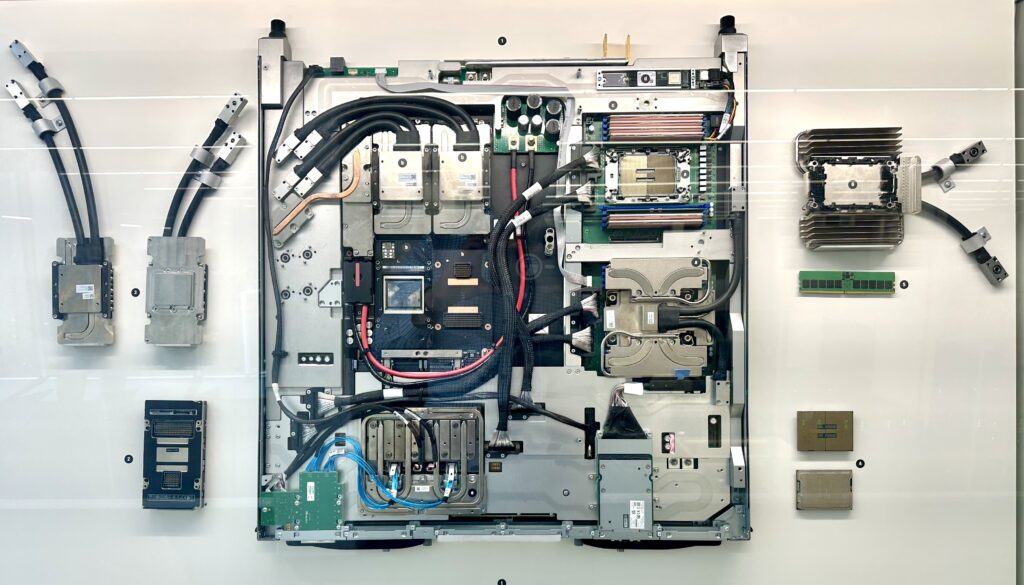
Featured photo: MareNostrum 5 GPU blade with glycol cooling, Barcelona Supercomputing Center, July 2025. Steve Jurvetson, via Wikimedia Commons, CC BY 4.0. Application illustration; no endorsement implied.
If coolant flow falls while a pump still draws current, what should the controller believe? That question connects AI-server liquid cooling directly to analog design: useful protection starts with measurements that distinguish a hydraulic fault from an electrical or sensor fault.
The topic is timely. Texas Instruments’ August 2026 cooling overview connects cold plates and coolant distribution units (CDUs) with sensors and motor control. Analog Devices’ May 2026 perspective treats cooling, power and telemetry as connected design concerns. These are vendor perspectives, rather than evidence that one architecture fits every installation.
Three design takeaways
- Choose measurements from the faults you need to distinguish.
- Match the interface, total error and detection latency—not just ADC resolution.
- Confirm hydraulic or mechanical response after issuing an actuator command.
Follow the coolant before choosing the IC
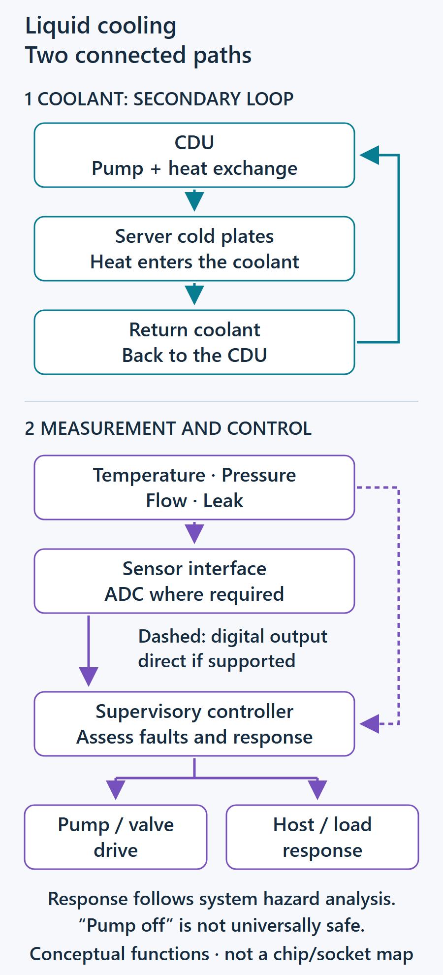
In a typical direct-to-chip arrangement, coolant flows through cold plates thermally coupled to processors. A CDU transfers heat between the secondary coolant loop and a facility cooling circuit. The specific topology and heat-rejection equipment vary. Supermicro’s server-to-CDU documentation provides one concrete equipment example.
The design task is to map measurement locations onto that physical path. Supply and return temperature, flow, pressure and local wetness can answer different questions. Pump current adds electrical evidence. Which channels belong at the CDU, manifold or server depends on branch layout, accessible interfaces and fault coverage. This is a design-review starting point, not a universal sensor checklist.
Start with the sensor’s electrical interface
TI’s October 2024 liquid-cooling application brief, SNAA422, discusses resistive leak detection, humidity, temperature, pressure, flow and pump-current monitoring. It supplies application examples; it does not qualify a complete cooling system.
For a resistive leak cable or pad, the interface must produce a distinguishable electrical response when the relevant coolant wets the sensor. An ADC can measure that response, while a comparator can support a threshold path. Neither alone proves that a cable is intact. Open-wire diagnostics need suitable excitation, circuit states and tests that distinguish a broken connection from a dry sensor.
An RTD needs excitation and a conversion path whose error budget includes lead resistance, self-heating, reference behavior and calibration. Integrated current sources and programmable gain can reduce external circuitry. They do not remove those error terms.
A raw pressure bridge may need excitation and amplification compatible with its differential signal and common-mode voltage. A conditioned industrial transmitter or digital sensor presents a different interface. First identify what the purchased sensor actually outputs; a separate precision ADC is not automatically required for every channel.
As a system-level reference, Sun and colleagues’ 2024 Frontier cooling dataset documents RTDs and an electromagnetic flow transmitter in field instrumentation. That demonstrates a real measurement arrangement, not a prescribed sensor set for an AI rack.
Budget accuracy and time together
An illustrative integrated component is TI’s ADS112C04, a 16-bit delta-sigma ADC with programmable gain and excitation current sources. Its functions are relevant to RTD and bridge interfaces. Component selection still requires checking input range, common mode, noise, conversion timing and the intended circuit.
A shared converter can reduce component count, but multiplexing adds channel timing differences. Filtering, settling, firmware polling and communications all contribute to the interval between a physical event and a usable decision. Include these delays in the fault-detection budget. Also consider what happens if the shared converter or its reference fails.
Pressure interpretation needs equally explicit boundaries. Name both measurement points—for example, CDU secondary supply and return—and establish the normal operating baseline. A pressure change across those points is not automatically the pressure change across an individual cold plate. Compare readings at relevant pump commands and operating conditions.
Current and commands need corroboration
A current-sense amplifier can reveal pump electrical loading, but current does not measure coolant flow. Interpret it alongside speed feedback, hydraulic measurements and drive status. The relationship depends on the pump and operating point; a single current trend is insufficient to diagnose a restriction or cavitation.
The actuator interface also determines the electronics. A pump assembly may expose a command input, while another design may require a motor-drive power stage. A valve may require voltage, current or another interface. A DAC generates a setpoint only within its specified capabilities; any additional scaling or power drive follows the actuator specification.
Check the result of the command using appropriate speed, flow or position feedback. The wider motor-control context is discussed in our inverter-control IC Insight; its generic architecture does not establish suitability for a particular coolant pump.
A decision aid for fault testing
These are engineering hypotheses to test, not automatic root-cause rules. Use representative equipment and coolant under controlled test conditions.
| Observation | Possible explanation | Corroborating check | Validation example |
|---|---|---|---|
| Measured flow falls | Pump, restriction, bypass or flow-sensor problem | Speed/drive status; pressure across named points; independent flow check | Controlled restriction or pump-command change within test limits |
| Local wet sensor responds | Coolant leak, condensation or contamination | Inspect the location; compare level and neighboring sensors | Representative coolant drip, contamination and cable-fault tests |
| Outlet temperature rises | Changed inlet temperature or load, reduced heat removal, or sensor error | Inlet/outlet readings; workload; flow; reference thermometer | Controlled load step and calibrated sensor comparison |
| One channel rails or becomes implausible | Sensor, wiring, excitation or front-end fault | Reference and excitation checks; known-good input | Open, short and overrange input tests |
Define the response before choosing thresholds
Monitoring and protection are related but distinct responsibilities. Specify who can alarm, limit workload, isolate a branch or change pump operation. The sequence and timing depend on the hazard and equipment; stopping a pump or closing a valve is not a universal safe response.
Where urgent protection is required, evaluate an independent response path with characterized latency. Confirmation and filtering must not delay that required action. Verify behavior during sensor failure, lost communications and power transitions as well as normal operation.
The useful analog design opportunity is therefore conditional and concrete: a defined sensor or actuator interface, a measurable error-and-time budget, and a tested failure response. Start with those requirements, then choose ICs. That connects cooling supervision to the broader power-delivery responsibilities described in our 48 V AI-rack Insight, without assuming either subsystem can protect the whole server by itself.
Selected primary sources
- Texas Instruments: data-center cooling overview — Vendor perspective on cold plates, CDUs, sensors and motor control.
- Analog Devices: data-center cooling — Vendor perspective on the relationship between cooling, power and telemetry.
- Supermicro: connecting a server to a coolant distribution unit — A concrete server-to-CDU connection example.
- Texas Instruments: liquid-cooling application brief, SNAA422 — Application examples for leak, humidity, temperature, pressure, flow and pump-current monitoring.
- Sun and colleagues: Frontier cooling dataset (2024) — Field instrumentation using RTDs and an electromagnetic flow transmitter.
- Texas Instruments: ADS112C04 product documentation — ADC functions, including programmable gain and excitation current sources, relevant to sensor interfaces.