
You are choosing the power module for a battery energy storage system (BESS) inverter. One supplier offers a mixed silicon and silicon carbide part, another offers a full silicon carbide part, and each datasheet carries a confident efficiency figure. Before you can compare them, you need to know what was measured, at what voltage and load, and where the measurement boundary was drawn. That question is sharpest for hybrid SiC modules: power modules that combine silicon and silicon carbide (SiC) devices in one package, where the label alone does not say which devices are which.
A few terms used below. SiC is a semiconductor material used for switches that, under comparable voltage, current, switching frequency and temperature, can lose less energy each time they turn on and off than comparable silicon switches. An insulated-gate bipolar transistor (IGBT) is a silicon switch widely used in high-power inverters. A metal-oxide-semiconductor field-effect transistor (MOSFET) is another switch type, and it can also be built in SiC. The power conversion system (PCS) is the equipment that converts the battery’s direct current (DC, current that flows in one direction) to the grid’s alternating current (AC, current that reverses direction many times per second) and back again.
Featured photo: Nirazuka Battery Storage Power Station, Isesaki, Gunma, Japan, photographed 1 November 2025 by Qurren, from Wikimedia Commons (file Nirazuka_Battery_Storage_Power_Station_3.jpg), licensed CC BY-SA 4.0. Displayed at responsive sizes, which may include resized renditions. Application context; installed power-module technology not established.
What onsemi and Sungrow announced
On 14 October 2026, onsemi announced that Sungrow adopted onsemi’s EliteSiC hybrid power-module technology for the Sungrow PowerTitan 3.0 storage platform, and onsemi reports peak inverter efficiency exceeding 99.3% (onsemi release). This is a vendor statement. The release does not give the load point or measurement boundary, and it cites no independent field measurement.
It also should not be read as the round-trip efficiency (RTE) of a whole storage system. RTE is the energy discharged divided by the energy needed to bring the system back to its starting charge, with all losses inside a declared system boundary counted (Long Duration Energy Storage (LDES) National Consortium factor matrix, a reference that defines this term; LDES means storage built to deliver energy over long periods). A converter figure is one input to that number, not the number itself.
What “hybrid module” means, and what it does not
In this article a hybrid module is a power module that mixes silicon and SiC semiconductor devices. That is a different thing from a hybrid inverter, the solar-plus-battery product that manages several energy sources. One term describes materials inside a package; the other describes equipment architecture.
Even among hybrid modules the mix varies. The onsemi NXH270A120M3F5SHG datasheet (July 2026, Rev. 0) documents one example: 1200 V SiC MOSFETs together with 1200 V IGBTs and diodes in a single module (datasheet). It is a technical example of a mixed module, not a statement of what sits inside PowerTitan 3.0. When you read a datasheet like this, ask which circuit positions use which device and how the converter is modulated; the device list alone does not settle that.
Three power-stage options, without a scoreboard
No row below wins by default. The table lists what to investigate and what evidence would let you decide for your own design.
On a small screen, scroll the table sideways to see every column.
| Power stage | Device mix, in plain words | Loss and cost tradeoff to investigate | Evidence needed |
|---|---|---|---|
| All-silicon | Silicon IGBTs and silicon diodes only. | Switching loss at the frequency you plan to run, and the filter and cooling size that follows from it. | Loss data at your voltage, current, frequency and temperature. |
| Mixed silicon-SiC (hybrid) | Silicon and SiC devices in one module; the exact mix differs by part. | Which positions use SiC, what that changes in loss, and whether the added device cost is justified at system level. | Part number and revision, device allocation, losses at matched conditions. |
| Full-SiC | SiC switches in all positions. | Whether lower switching loss pays for the device cost, and how gate drive and protection are handled. | The same matched-condition data, plus drive and protection limits. |
Where the efficiency boundary sits
Texas Instruments’ design guide for an 11 kW bidirectional inverter reference design shows why a loss figure travels badly. Conduction loss, switching loss and diode loss depend on current, voltage, switching frequency, gate resistor and temperature, so a number only transfers to your design when those conditions match (loss estimates, section 2.3.1.5). The same guide’s efficiency test setup lists its measurement equipment and a separate 12 V supply for the device under test, a useful reminder to ask what an efficiency figure includes (test setup, section 3.2.4).
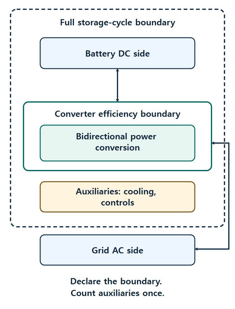
Two boundaries are worth separating. Converter efficiency covers the conversion block at a stated operating point. Storage-cycle energy covers everything inside the declared system, from charge in to energy out. The LDES Consortium matrix lists auxiliary consumption, such as lighting and controls, as energy use beyond what the RTE calculation already reflects. So say where auxiliaries sit in your accounting and count them once.
Sungrow, Hefei and a supplier evidence checklist
The announced example involves Sungrow, whose contact page identifies its headquarters in Hefei, Anhui, China (Sungrow contact page). The headquarters location is the only China-specific fact this article draws on; it implies no further sourcing relationship, bill-of-materials detail or relationship with ChinaSemiOps. The checklist below applies to any module supplier in any country.
Questions to put to a module supplier
- Which exact part number and revision, and which device sits in each circuit position?
- What are the losses at matched voltage, load, switching frequency, temperature and power-flow direction (charging and discharging)?
- What efficiency boundary and load profile sit behind the headline figure?
- What thermal interface, power cycling (devices heating and cooling as the load rises and falls) and mission profile (the electrical and environmental stresses expected in service) assumptions apply?
- What gate-drive and protection limits come with the part?
- Which reliability tests were run, under what conditions, and who owns change notices and traceability?
Reliability and cost: ask for dated, comparable evidence
A mission profile describes the electrical load, temperature and humidity a product sees in service, and Infineon’s reliability whitepaper ties wear-out assumptions to it (Infineon whitepaper). In a BESS the load swings matter. An Infineon engineer explains that grid overload conditions cause power cycling, which becomes thermal cycling and stresses the chip, bond wires and substrates down to the heat sink (Infineon podcast transcript). That is a vendor’s engineering explanation, not a promised lifetime, and it is a good reason to ask for thermal and mission-profile evidence for your duty cycle.
Cost needs the same discipline. A module price leaves out costs that move with loss, such as heat sinks, filters and enclosures. Compare dated quotations with the same scope and the same system boundary, rather than assuming any option is cheaper in general.
A practical next step
Build a one-page comparison sheet with your operating voltage, load profile, switching frequency, coolant or ambient temperature and power-flow direction, then ask each supplier to fill in the same rows. For the control and drive side of the same decision, see our related reading on inverter control integrated circuits and the power analog stack and on isolated gate drivers.
Selected primary sources
- onsemi news release, 14 October 2026: the Sungrow PowerTitan 3.0 adoption announcement and the vendor-reported efficiency.
- onsemi NXH270A120M3F5SHG datasheet, July 2026 Rev. 0: a documented example of a mixed SiC MOSFET and IGBT module.
- LDES National Consortium competitive factor matrix: definition of round-trip efficiency and auxiliary consumption.
- Texas Instruments TIDUE53J, section 2.3.1.5: loss mechanisms and the operating parameters they depend on.
- Texas Instruments TIDUE53J, section 3.2.4: an explicit efficiency test setup.
- Infineon reliability modeling whitepaper: mission profile and wear-out assumptions.
- Infineon BESS power conversion podcast: power cycling and thermal stress in storage inverters.
- Sungrow contact page: the company’s stated headquarters location.
Please link to this article when sharing. Contact us for permission to republish the full article.