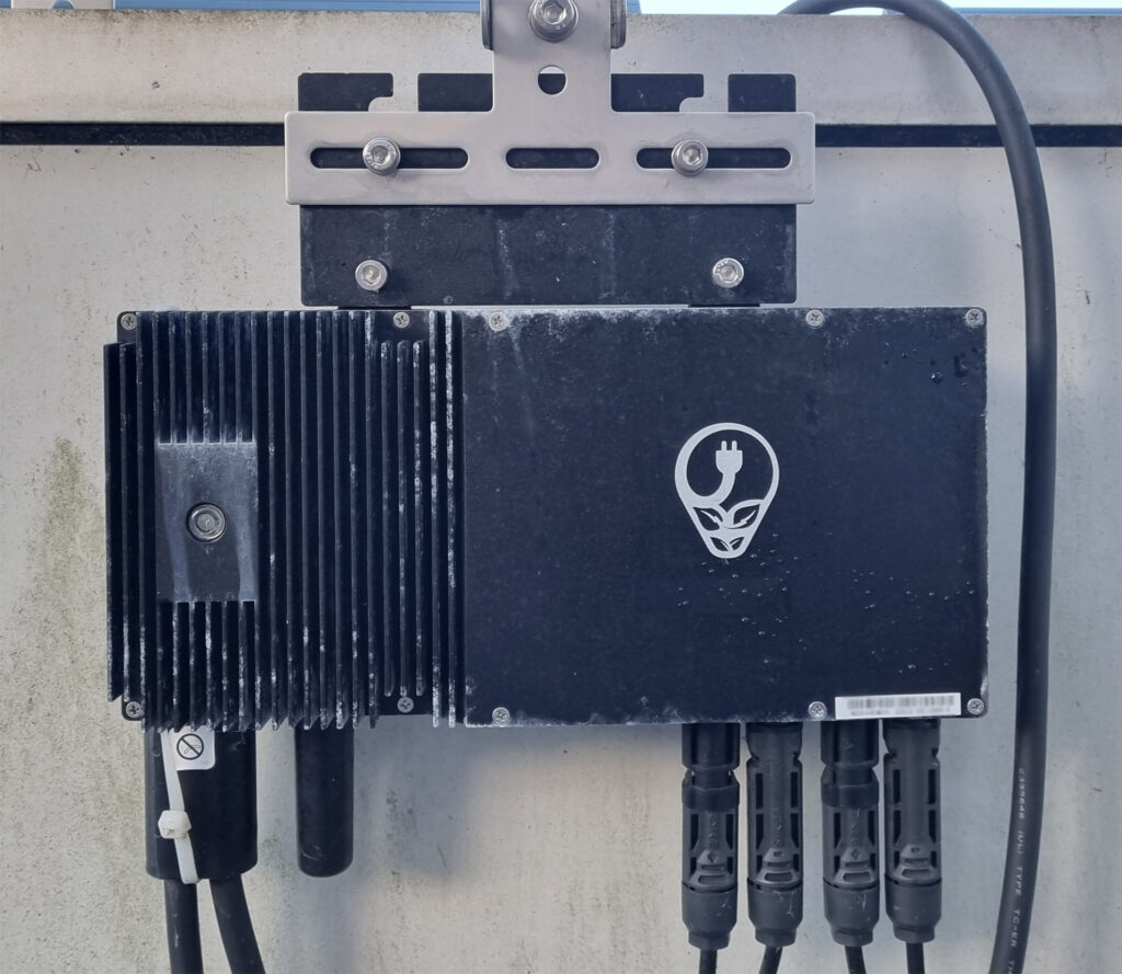
A balcony-solar microinverter, shown as application context only; the photo does not identify the devices inside. Photo: © Michael Paetzold (Michael32710) / Wikimedia Commons, September 8, 2025, Creative Commons Attribution–ShareAlike 4.0 (CC BY-SA 4.0). We resized it for display; no crop or retouch by us. This photo license is separate from the reuse notice at the end of the article.
Suppose a stage in your solar microinverter uses two separate switches connected in opposition, a back-to-back pair, so it can block voltage of either polarity when off. A microinverter is a small inverter that turns a solar panel’s direct current (DC) into alternating current (AC), the kind a grid supplies. A supplier now offers a bidirectional GaN switch as a replacement. GaN (gallium nitride) is the semiconductor material, and a bidirectional switch (BDS) is one device built to block voltage in both directions. Can you keep your gate driver (the circuit that drives a switch’s control terminal, its gate), your protection scheme and your fault tests?
Check the exact part before reusing them. The documented two-gate examples define each gate voltage against its associated source, a main current terminal. The IGLT65R110B2 (110B2) datasheet specifies gate current as well as voltage, while transitions and fault responses remain responsibilities of the converter, the circuit that converts electrical power. Three Infineon documents for 650 V parts provide examples; the closing worksheet turns these checks into supplier questions.
Three takeaways
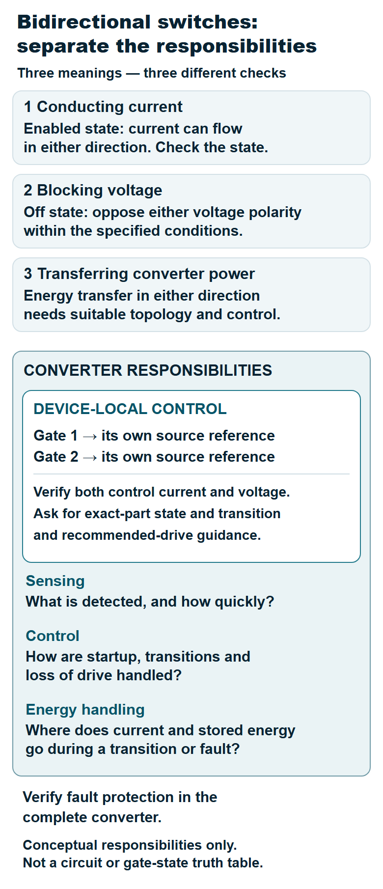
- “Bidirectional” can mean three separate things: current conduction when the switch is enabled, voltage blocking in the off state, and energy flow through the converter. An exact part’s datasheet can establish the first two within its stated conditions; converter power flow needs a system-level check.
- Each gate in the documented two-gate examples has its own source reference. The 110B2 datasheet specifies gate current as well as voltage. Maximum ratings and test thresholds are limits and measurement points, not recommended drive settings.
- Converter qualification assesses the design against specified requirements and operating conditions. It includes transitions, lost-drive behavior and fault response. Ask the supplier for evidence for the exact part and circuit.
“Bidirectional” means three different things
Enabled current conduction. With the switch commanded on, current can flow through it in either direction. But Infineon’s demo-board guide for the IGLT65R055B2 (the “55B2”) identifies four operating modes: on, off and two diode modes, in which the switch is actively controlled to behave like a diode. Check how each mode conducts and blocks against the exact part’s state and polarity table.
Off-state polarity blocking. The final IGLT65R110B2 datasheet (Revision 1.2, October 20, 2026) describes efficient voltage blocking in both directions. Its maximum-ratings table lists source-to-source voltage, the voltage between the device’s two source terminals, separately as continuous, transient (temporary voltage excursions) and surge (brief overvoltage events), each with its own value and test conditions. Table 2 gives a continuous rating below the 650 V transient rating; the transient and surge ratings apply for their stated durations. Match the actual waveform to that table; the datasheet also warns that continuous application of maximum ratings can deteriorate lifetime.
Converter energy direction. Whether a complete converter can move energy both ways depends on its circuit arrangement (topology), its control and its verified operating range. Infineon’s application note AN211819 describes one 500 W solar microinverter reference design with a defined input and output. Check energy direction against the complete converter specification.
Each gate keeps its own source reference
The 55B2 guide calls the device a five-terminal device: two gates, two sources and a substrate, the silicon base layer on which the device is built. A gate is the control terminal; a source is a main current terminal. The guide’s figure labels the control voltages VG1S1 and VG2S2, gate-to-source voltages (VGS): gate 1’s voltage is measured against source 1, and gate 2’s against source 2. “Referenced to” here means measured against, not wired to.
A back-to-back pair also has two gate-and-source pairs. You still need to define each gate’s reference when both switches share one device. Determine the number of isolated channels (electrically separated driver outputs) and supplies from the converter circuit.
The substrate needs separate attention. The 110B2 datasheet says its substrate thermal pad, the pad that conducts heat out of the package, is for thermal coupling only and should be electrically isolated from any electrical node in the system by isolation material. The 55B2 guide’s device symbol shows a substrate terminal. Use mounting and electrical-isolation instructions for the exact part.
A GIT gate is driven by current and voltage
The 110B2 datasheet describes a gate injection transistor (GIT) structure, Infineon’s gate design for normally off GaN switches that is driven with a specified gate current as well as a gate-to-source voltage. Normally off means the switch stays off unless driven. Consider both current and voltage when designing the drive.
Its gate-related entries include a steady-state gate-current limit for each single gate, a separate pulsed limit with its own pulse conditions, negative gate-to-source voltage limits, on-resistance (the switch’s resistance when on) measured at a stated gate current, and two gate thresholds, the levels at which the state changes under test: off to diode mode, and diode mode to on.
Keep three roles separate when selecting bias, the applied control current and voltage: a maximum is a limit, a measurement current is a test condition, and a threshold marks a state change under test. None is automatically a recommended drive setting. The datasheet points to Tables 8 and 9 and a gate-drive application note. Read those references and the manufacturer’s recommended drive guidance before choosing settings for the exact part.
Infineon’s microinverter note describes one implementation: in its 55B2 reference design, an isolated gate drive (output electrically separated from the control side) built around the 2EDR7259X driver provides a negative gate-to-source voltage, which the note says gives safe off-states during switching transients and protects against spurious turn-on, meaning unintended turn-on. Treat this as a vendor-described 55B2 board implementation; confirm the manufacturer’s 110B2 drive guidance separately.
Transitions and faults are converter-level work
Commutation is the transfer of current from one circuit path to another. To assess it, ask for the exact part’s complete state table, transition timing and fault-interruption sequence under the relevant current and voltage polarities. The selected pages do not cover all of these details.
Soft switching arranges a transition with device voltage or current at or near zero; hard switching changes state while substantial voltage and current overlap. Zero-voltage switching (ZVS) is the voltage-near-zero case. The microinverter note ties its reference-design efficiency to ZVS over a wide range of line and load. The 55B2 demo guide limits its board to AC soft-switching demonstrations and excludes hard-switching conditions. Both documents say their boards are not qualified for safety, manufacturing, or operation over the entire temperature range or lifetime. Use their board-specific conditions, including the demo’s power-on order, as context for your own converter evaluation.
The converter design must establish how quickly a fault is detected, where inductive current goes after turn-off, the resulting voltage overshoot (a brief rise above the intended voltage), and behavior at startup, shutdown and loss of drive supply. Ask for measured fault response, compliance evidence and short-circuit withstand time: how long the device tolerates a short circuit under specified test conditions. Your converter still needs measured evidence for these outcomes.
Where the 900 V announcement fits
According to Infineon’s October 26, 2026 release, new 900 V GaN bidirectional switches have been tested and are being integrated into product development at Enphase Energy, an energy technology company. Production qualification is expected to follow. Assess the 900 V devices using their own drive, mounting and qualification evidence, separately from the 650 V examples. The worksheet below applies to either voltage class.
China-based examples to compare separately
China-based activity spans different device classes. Innoscience describes its V-GaN bidirectional platform as 30–120 V and in mass production. Its location page lists Suzhou as headquarters and a manufacturing site, with another manufacturing site in Zhuhai. A 2025 paper by researchers affiliated with ShanghaiTech and Donghua universities reports an experimental GaN bidirectional switch built on a single chip.
These are separate comparison entries. The low-voltage platform and research prototype do not establish drive requirements for the 650 V gate injection transistor examples or the announced 900 V devices. Use the same worksheet for any supplier: obtain the exact part’s current datasheet, gate-drive guidance, state table and qualification evidence before comparing it with your converter’s needs.
A supplier evidence worksheet
Use this with any supplier. For each answer, record the exact part and revision, the source page, the test conditions, and whether it is measured data, a vendor statement or your own inference.
| Question | Evidence to request | Not established by the cited pages |
|---|---|---|
| Which part and revision? | Revision, date, change notices | Equivalence of a different part or revision |
| Which gate and source references apply? | Terminal definitions; substrate or thermal-pad treatment for this part | Mounting and isolation instructions for another part |
| What drive is recommended? | Gate current and voltage waveforms, off bias, driver network, with test conditions | A complete drive recommendation for the selected part |
| Which states block or conduct each polarity? | Part-specific state and polarity table, including diode modes | Complete state-to-polarity mapping for the selected part |
| How do transitions behave? | Allowed soft- and hard-switching conditions, timing, measured overshoot in a similar circuit | Transition limits in your circuit |
| What happens on fault or lost drive? | Detection point and delay, turn-off path, inductive-energy path, startup, shutdown and supply-loss tests | Measured fault and lost-drive response in your circuit |
| Which ratings fit my waveform? | Continuous, transient and surge limits with duration, temperature, repetition | Rating fit for your waveform |
| What is qualified? | Device qualification records; your own converter safety, production and lifetime plan | Qualification of your converter |
Next action: send these eight questions to the supplier in writing, name the exact part and revision, and file each answer with its source page and its status as measured, vendor-stated or inferred.
For broader background on integrated circuits (ICs, circuits built on one chip), see our Insights on GaN power IC integration boundaries, isolated gate drivers and solid-state transformer power IC opportunities. This article stays on control states and transitions.
Selected primary sources (checked October 31, 2026)
- Infineon: IGLT65R110B2 final datasheet, Revision 1.2, October 20, 2026 — ratings, gate characteristics, substrate thermal-pad note.
- Infineon: UG090038 V1.2, April 24, 2025, DEMO_AC_ZVS_HVBDS demo board user guide for the IGLT65R055B2 — terminals, four modes, soft-switching scope, reference-board notice.
- Infineon: AN211819 V1.1, September 18, 2025, 500 W solar microinverter reference design — gate-drive description, ZVS, reference-board notice.
- Infineon: technology news, October 26, 2026 — 900 V status.
- Innoscience: V-GaN Bi-Directional platform overview — vendor-stated voltage range and production status.
- Innoscience: Global Presence — company-stated Suzhou and Zhuhai locations and roles.
- ShanghaiTech-hosted author paper, Applied Physics Letters 127, 163305 (2025) — experimental single-chip GaN bidirectional switch; university affiliations.
Educational background based on selected pages; use the exact part’s current manufacturer guidance and validate your converter under its intended conditions.
Please link to this article when sharing. Contact us for permission to republish the full article.