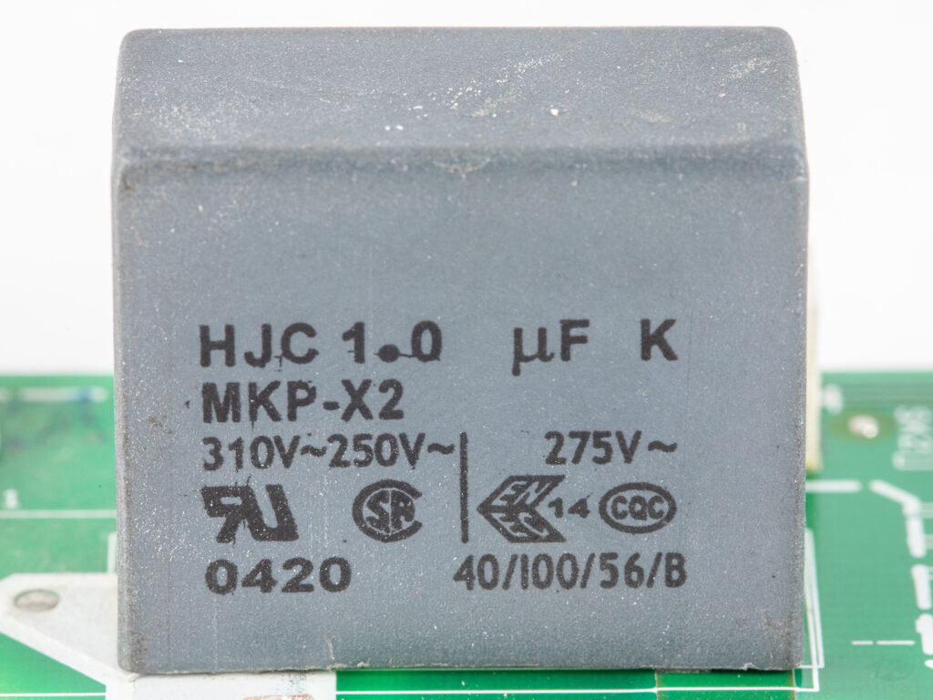
An X2-class capacitor (X2 is a subclass of X-class safety capacitors) mounted on a power-supply board. Component illustration only; the photograph does not identify the discharge circuit used. Photo: © Raimond Spekking / CC BY-SA 4.0 (via Wikimedia Commons).
Picture a laptop power adapter left plugged into the wall with nothing connected to it. The output is idle, yet a resistor across its AC (alternating current) input may still be turning a little power into heat, around the clock. That resistor is there to drain the input filter capacitor after the plug is pulled. X-capacitor discharge circuits keep that drain but connect it only after AC disappears, trading lower connected loss for extra sensing and control that the design and its suppliers must prove.
Three takeaways
- An always-connected bleed resistor (a resistor placed across a capacitor to drain it) is simple, but it wastes power whenever the supply is plugged in.
- Controlled discharge removes that standing loss from the resistive path. It adds sensing delay and its own small consumption, so it does not make a supply "zero standby".
- Ask for evidence on the exact circuit: part variant, datasheet status, measured unplug waveform and measured no-load input power.
Why the input filter capacitor needs a discharge path
A power supply's AC input usually has a filter that keeps switching noise off the mains. One part is an X-class safety capacitor connected between the line and neutral conductors (X is a class letter, not an acronym). Texas Instruments (TI) describes it as helping filter differential-mode noise, meaning noise between those two conductors (TI application report SLUA968). Keeping that noise down is an EMI (electromagnetic interference) task.
After the plug is pulled, the capacitor can keep its charge. TI's datasheet frames the goal as voltage not remaining on the AC plug pins indefinitely (TI UCC25640x datasheet, section 7.4.2), so the design needs a discharge path. How far and how fast the voltage must fall depends on the applicable end-product standard and edition. This article quotes no threshold, and it covers only the capacitor across the AC input, not large capacitors further downstream.
What a constant bleed resistor costs
The simplest discharge path is a resistor across the X capacitor. It needs no control, but both TI documents note the cost: it dissipates power the whole time the supply is connected to AC (SLUA968; UCC25640x datasheet). In a low-standby design, that standing loss is one visible contribution to input power. Here, standby means equipment that is idle but plugged in, and no-load means the supply is running with nothing drawing from its output.
Choosing the value is a compromise. A larger X capacitor can ease filtering but needs a lower resistance for the same discharge speed, which wastes more power. A higher resistance saves power but discharges slowly. TI calls this a trade-off between standby power and EMI performance.
How fast the voltage falls depends on both the resistance and the capacitance. The time constant is the usual yardstick for that decay speed. It is not the time to reach zero volts, and it is not the time to reach a safe level.
Controlled discharge: two states and one extra job
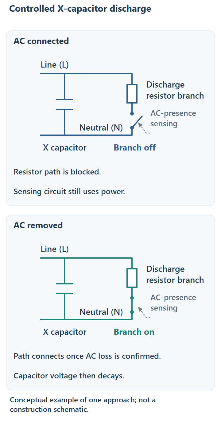
In the resistive approach shown in the conceptual figure below, controlled discharge gives the discharge path two states:
- AC connected: the discharge path is blocked or idle, so no steady current flows through it.
- AC removed: once the circuit confirms AC is gone, it connects the path and the capacitor voltage decays.
Not every controlled-discharge implementation works this way; the integrated TI example later in this article discharges differently.
The extra job is sensing. The time between unplug and connection is the sensing delay, and it adds to discharge time. Total decay therefore depends on detection plus discharge in the exact implementation; the time constant alone does not predict it. The sensing circuit also consumes some energy, and other supply losses remain, so lower loss in this branch is not zero standby for the whole supply.
Constant bleed versus controlled discharge
| Constant bleed resistor | Controlled discharge | |
|---|---|---|
| AC connected | Current flows through the resistor continuously | Discharge path blocked or idle; sensing still draws some power |
| After unplug | Discharge begins at once, at a speed set by resistor and capacitor | Begins after AC loss is confirmed; total time includes that delay |
| Added function | None | Sensing and control, standalone or inside a controller |
| Check first | Standing loss versus EMI trade-off | Sensing delay, tolerances, fault behaviour, exact variant |
Two vendor examples: standalone and integrated
These illustrate how the function can be packaged. They are not a drop-in comparison, a recommendation or an endorsement.
Standalone: CAPZero-4 (CAP400DG), Power Integrations. In its datasheet (Rev. A, June 2026, marked PRELIMINARY, so details may change), the IC (integrated circuit) blocks current through external discharge resistors while AC is connected, then connects them after AC is disconnected (Power Integrations datasheet). The resistors stay in the design: the document says their values set the discharge time, and its layout and safety sections discuss discharge energy sharing and fault conditions. Check for a newer revision before relying on it.
Integrated: UCC256404, TI. Its datasheet (SLUSD90F, revised August 2026, status label "production data") lists the UCC256404 power-supply controller as having integrated X-capacitor discharge. The feature is not present across the whole family, so verifying the exact part number and variant matters. Seeing integration as an alternative to adding a separate discharge IC is this article's interpretation, not a statement from TI, and it is not a performance or equivalence claim.
TI describes detecting AC loss by monitoring zero crossings (the moments the AC voltage passes through zero) through a high-voltage sensing input. Once loss of AC is confirmed, an internal current source discharges the capacitor. That is a different mechanism from the switched resistor in the figure above.
Supplier evidence checklist
This list applies to any supplier relationship, in China or elsewhere. The public documents behind this article do not tie controlled discharge to a particular country or supplier base. Controller suppliers answer the first items, capacitor and resistor suppliers the ratings, the converter designer the measurements, and the equipment manufacturer the compliance questions.
- Exact part number, suffix and variant, and whether that variant includes the discharge feature.
- Datasheet revision, date and status (preliminary or production).
- Schematic showing each X capacitor and its discharge path: passive resistor, standalone IC or integrated controller.
- Residual voltage at the plug terminals versus time, with line voltage and frequency, disconnect phase (the point in the AC cycle where the plug is pulled), capacitor tolerance, sensing delay and the full waveform under justified worst-case conditions.
- Whole-supply no-load and standby input power with load mode, line conditions and method, plus a comparison that isolates the discharge circuit's share.
- For external resistors: voltage, energy and thermal ratings, tolerances and fault-test records.
- Layout and surge-protection review, and what triggers re-evaluation when a part changes.
- The applicable finished-equipment standard and edition, its acceptance criteria, and test evidence for the exact finished equipment. Keep the supporting documents for an individual component separate from that finished-equipment test evidence.
What to do next
Start with your own schematic: mark the discharge path for each X capacitor. Then measure two things on the exact build: the voltage at the plug terminals after unplugging, and whole-supply no-load input power. Those two results show whether the lower standing loss is worth the added sensing delay, and they give supplier conversations a shared reference.
Related reading
Related power-stage background from ChinaSemiOps:
Selected sources
- Power Integrations, CAPZero-4 (CAP400DG) data sheet, Rev. A, June 2026, preliminary. Standalone operation and external resistor responsibility.
- Texas Instruments, SLUA968, Minimize Standby Consumption for UCC287xx Family, August 2019. Foundational explanation of the X capacitor, bleed resistor and standby trade-off; background, not a current standards reference.
- Texas Instruments, UCC25640x LLC Resonant Controller datasheet, SLUSD90F, revised August 2026. Device comparison table and section 7.4.2 on discharge. LLC is a resonant converter type named for its inductor-inductor-capacitor network.