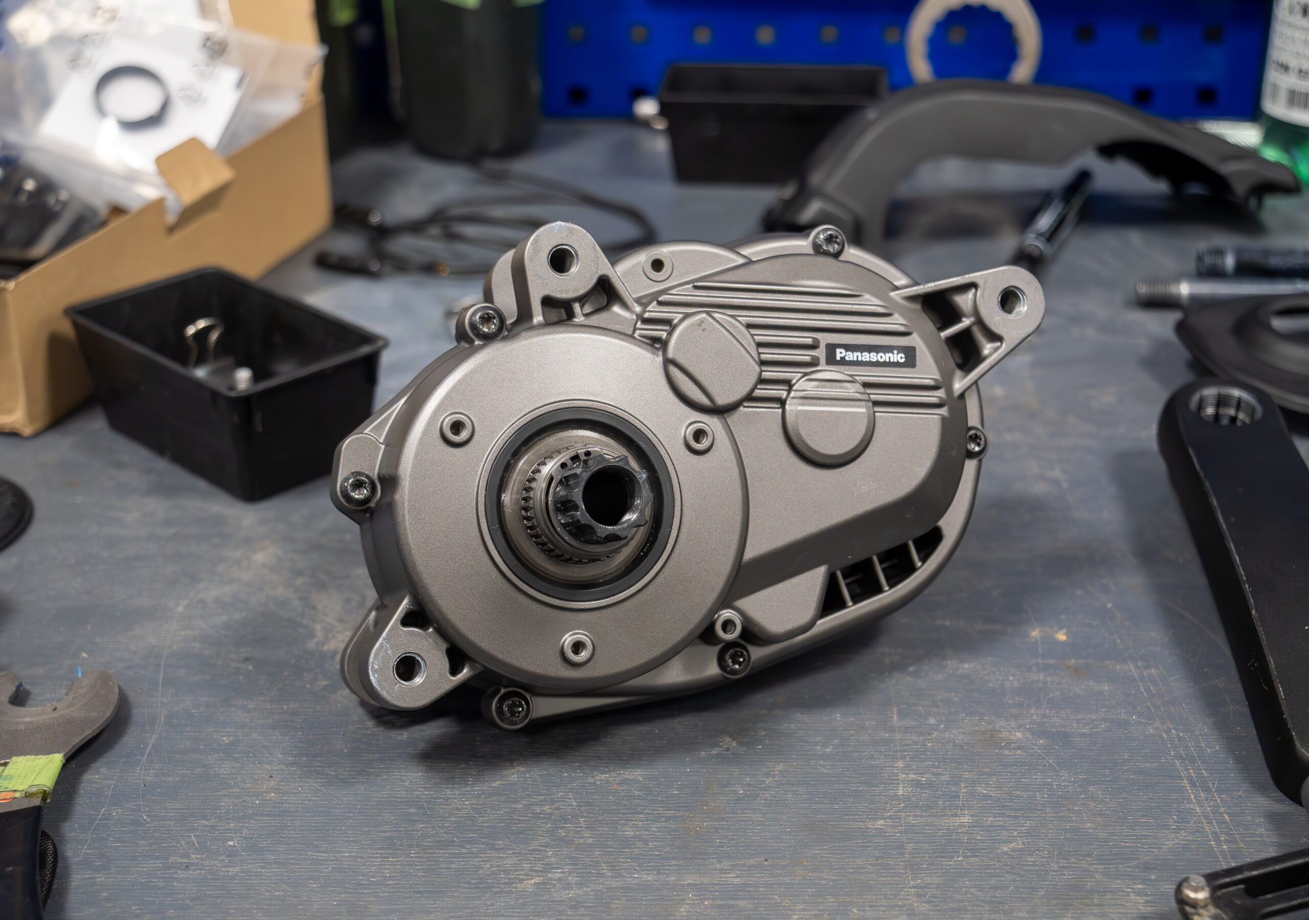
A current sensing output spikes just as a motor inverter, the switching stage that drives the motor windings, changes state. Did the phase current change, did the sensing circuit add error, or both?
This article follows a hypothetical motor drive with a nominal 48-volt (48 V) supply and a generic current-sense amplifier. It gives analog and power engineers a way to judge when a reading near a switching edge can be trusted, and a checklist of evidence to request. It covers analog sensing only.
Three takeaways
- A spike can be real current, sensing error, or both.
- Sense the shunt through two separate connections, and check real input excursions, not only the nominal 48 V.
- Choose the allowed error first, then find when the whole chain enters and stays inside it.
A spike at the switching edge: what does it actually measure?
Motor phase current ripples, follows the load, and can flow in either direction. A switching edge is the moment a power switch turns on or off. In pulse-width modulation (PWM), which varies pulse on-time to control the drive, edges repeat constantly and the motor-terminal voltage jumps quickly at each one.
Three effects can then appear on the output together: the real current change, the amplifier’s response to the fast voltage step shared by both inputs, as explained in Analog Devices’ common-mode step-response note, and pickup—unwanted voltage coupled from nearby changing currents or voltages. Residual error, used below, is the difference between the measured output and the ideal output for the actual current, which may itself be changing. For the stage creating these edges, see inverter control chips and the power-analog stack.
Keep the shunt voltage separate from the switching voltage
A shunt is a low-value resistor in the current path; the voltage across it indicates the current. That voltage is the differential voltage, the difference between the amplifier’s two sense inputs. Both inputs can also sit at a much larger voltage that follows the motor terminal. The common-mode voltage is the average of the two input voltages relative to the amplifier’s reference potential, normally its ground. It steps at each edge.
A Kelvin connection, also called a four-terminal or force-sense connection, separates the path carrying current from the wires sensing voltage. Take the two sense connections directly from the shunt terminals, short and close together, away from current-carrying copper and switched-current loops. This reduces error from current-carrying copper; it does not eliminate pickup.
The output reference is a separate voltage applied to the amplifier’s reference input. It sets the zero-current output level, allowing a suitable output range to represent current in either direction above and below that level.
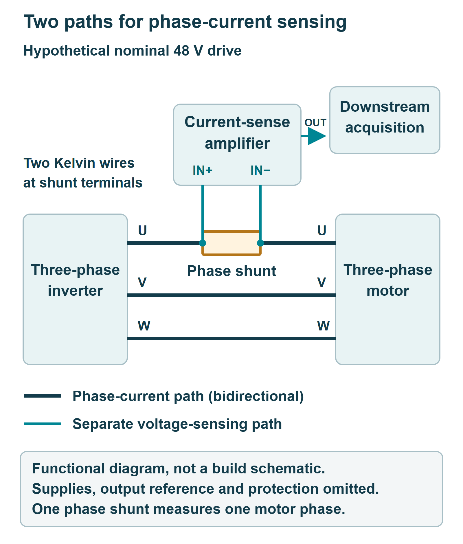
Check the shunt location: one phase shunt measures one motor phase, not three currents.
Also check each input’s actual voltage excursion, including undershoot (a dip below the intended level, for example below ground) and ringing (oscillation around the final voltage), against the device’s recommended operating conditions. Absolute maximum ratings are stress limits, not guaranteed measurement accuracy. A nominal 48 V bus does not prove an amplifier’s input range fits.
DC accuracy does not tell you when the reading is usable
The common-mode rejection ratio (CMRR) describes how strongly an amplifier suppresses a voltage shared by both inputs, compared with its response to the differential voltage. It is usually quoted for DC (direct current), a steady voltage rather than a fast edge, so it does not establish behavior after a switching edge. Bandwidth, the frequency range of a specified signal response, likewise does not mean immunity to common-mode steps. During overload recovery, the return to valid operation after an overload, the output can be invalid.
Ask when the output becomes usable. Choose the allowed measurement error first. Then find when the complete chain enters the chosen error band and remains inside it; that is settling, and touching the band once does not count. Downstream acquisition is the process of sampling the amplifier output. The sampling circuit needs a valid signal throughout its acquisition interval. It must fit between settling and the next disturbance, allowing for timing uncertainty.
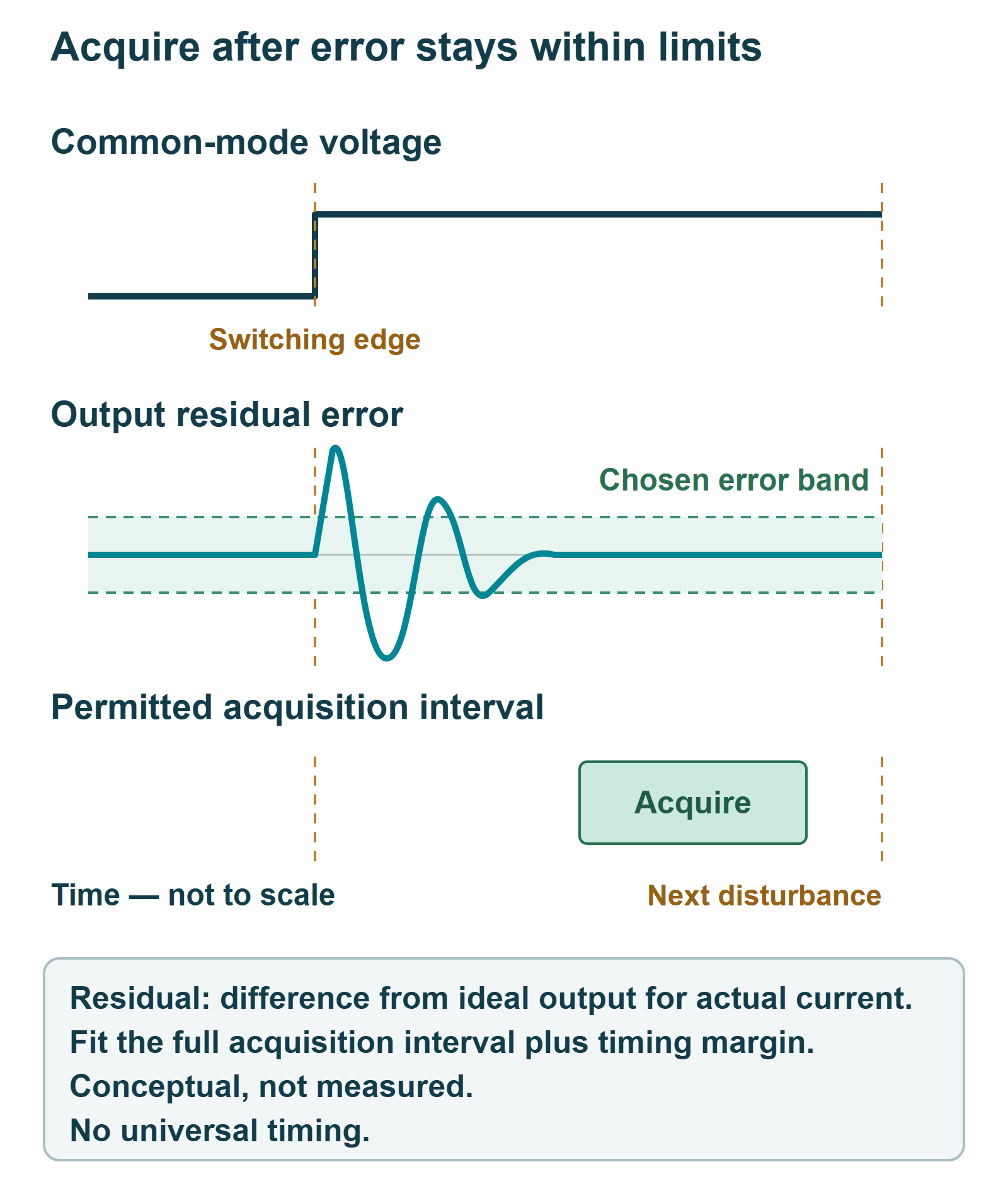
Blanking, temporarily not using readings, can keep an invalid interval out of the control loop but does not remove the physical error. Do not pick a blanking interval from one typical plot; match the conditions in the checklist below.
Filtering helps only when the response still meets the timing budget
A filter can reduce high-frequency disturbance, but it slows the response. At the input, added series resistance can create gain error; the INA240 datasheet, section 9.1.1, states that input filters are not required and not recommended for that part. That is part-specific guidance, not a universal ban.
At the output, a filter changes the impedance—the opposition to a changing electrical signal—that the downstream circuit sees, and adds delay. It cannot repair saturation, where the amplifier reaches an output limit and stops faithfully reproducing the signal. That clipped output must recover first. Small-signal settling instead follows a small change while the amplifier stays within its normal operating range, without overload. Check the filter’s effect on settling, amplifier stability and downstream loading; do not copy component values from another design.
Compare supplier evidence under the same conditions
One public example: 3PEAK, whose company information identifies headquarters in Suzhou, China, positions its TPA133 for current sensing with enhanced pulse-width-modulation rejection—the vendor’s term for limiting output disturbance from PWM common-mode steps—in motor and solenoid applications (datasheet revision A.1, 20 August 2025). That supplier description is a starting point: request the transient test conditions and the error criterion needed for your own design. Headquarters location says nothing about where parts are made or about any relationship with ChinaSemiOps.
This checklist is generally applicable to any amplifier or shunt supplier, board designer or module test team.
| Match this | Ask the supplier | Check in your design |
|---|---|---|
| Input excursions | Operating range, separate from absolute maximum | Actual undershoot and ringing |
| Common-mode step | Step size and edge speed behind any plot | Your edge speed and swing |
| Gain and signal | Gain and differential signal used | Your gain and changing current |
| Supply, output reference, load, temperature | Values used for the plot | The same on your board |
| Filter and downstream load | Whether a filter was fitted | Filter plus full acquisition interval |
| Error criterion | The band that defines “recovered” | Your allowed error; enter and remain |
| Guaranteed or typical | Which limits are guaranteed | Which one your margin relies on |
Your next step: write down the allowed error and the matched conditions, then compare them with a measurement in your own drive. Keep probe and ground-lead pickup separate from the true signal. A bandwidth or DC rejection figure alone does not establish recovery after a switching edge. Treat any unmatched condition as unknown.
Further reading
Isolated gate drivers for high-power switches covers the circuits that turn power switches on and off, the gate-drive side of fast switching edges.
Selected primary sources
- Texas Instruments, SBOA170, shunt and Kelvin connection application note (original October 2016; revision D, April 2023; accessed 22 October 2026).
- Analog Devices, AN-1308, Rev. A, October 2015 (older foundation source on common-mode step response).
- Analog Devices, AN-1321, Rev. 0 (older foundation source on input excursions; publication month not established).
- Texas Instruments, INA240 datasheet, SBOS662C, December 2021, section 9.1.1.
- 3PEAK, TPA133 datasheet, Rev. A.1, 20 August 2025 (date from the PDF revision history).
- 3PEAK, About 3PEAK (headquarters location; accessed 22 October 2026).
Photo credit
The featured photo shows a prototype mid-mounted pedelec (pedal-assist electric bicycle) motor on a workbench, used here only as motor-drive application context. It identifies no current measurement, fault or 48 V operation. Photo: Matti Blume / MB-one, Wikimedia Commons, CC BY-SA 4.0; taken 10 April 2025, source crop retained, resized for display. The photo license is separate from the reuse notice below.
Please link to this article when sharing. Contact us for permission to republish the full article.