Megawatt charging is not simply a larger connector problem. At the charger output, a practical safety architecture may need to compare voltages, monitor insulation, confirm contactor state, watch connector temperature and trigger a dependable shutdown—all while the energy path operates at exceptionally high voltage and current.
That makes the Megawatt Charging System (MCS) interesting to analog and mixed-signal designers. The plausible opportunity is not an IC that carries megawatt power. It is a safety measurement AFE or multi-die package that coordinates sensing and diagnostics while external high-voltage networks, transducers and interrupters do the physical work.
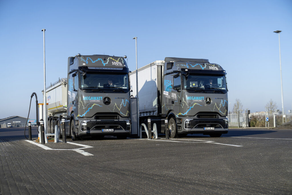
Featured image: Mercedes-Benz eActros 600 test trucks at a charging site during the January 2026 MCS test program. Photo: © Daimler Truck AG (26DT002_001), released 20 January 2026; used under the newsroom’s editorial-use terms.
Three takeaways
- Standards maxima and commercial operating points are different numbers.
- Insulation, voltage, contactor and thermal supervision form the most interesting silicon boundary.
- Custom integration must beat qualified modules without weakening independent protection.
What changed for the Megawatt Charging System in 2026?
IEC 61851-23-3:2026, published in August, covers MCS electric-vehicle supply equipment with a rated maximum of up to 1,250 VDC on the vehicle-facing side. Its public description also calls for protective separation between the supply-network side and the vehicle side. It says requirements for bidirectional power flow remain under consideration.
The connector envelope is different. IEC TS 63379:2026, published in January, covers the MCS connector, inlet and cable assembly at ratings up to 1,500 VDC and 3,000 A. Thermal sensing—or thermal transport combined with sensing—is part of that connector architecture.
In July, ISO 15118-20 Amendment 1 added an MCS service and an improved security concept. Yet publication does not make every implementation interchangeable. At its May Testival, CharIN reported four MCS vehicles, seven EVSEs and four test systems, while identifying coupler compatibility and line-lock reliability as areas for improvement. CharIN Testival Europe 2026
| Layer | Published or vendor-stated envelope | What it means |
|---|---|---|
| MCS EVSE | Up to 1,250 VDC vehicle-side | Equipment-standard maximum, not every charger’s operating point |
| Coupler and cable | Up to 1,500 VDC and 3,000 A | Interface envelope; do not multiply into a universal charger rating |
| MAN eTGX/eTGS | Up to 750 V, 1,000 A, 750 kW | Vendor-stated series-vehicle capability |
| ABB MCS1200 / M1200 | Up to 1.2 MW and 1,500 A; 150–980 V output | Vendor-stated charger family envelope |
These figures are not contradictions. A connector needs a broad interface envelope, an EVSE standard defines a safety boundary, and each product selects an operating range within its system design. MAN publishes the 750 V, 1,000 A and 750 kW vehicle figures; ABB publishes the 1.2 MW and 1,500 A MCS1200 figures and the related 150–980 V M1200 range. For an IC, “1,500 V rated” is therefore not a complete specification: working voltage, transients, insulation type, creepage, clearance and environmental conditions still matter.
Follow three paths across the output boundary
The energy path runs from the converter and isolated DC bus through contactors, a cooled cable and connector, then into the vehicle pack. The measurement path asks whether that sequence is safe. A third path must command shutdown when it is not.

This separation matters. Voltage dividers, insulation-monitor injection impedances, isolation barriers, magnetic current sensors and high-current switching structures cannot disappear into an ordinary precision-analog die. A protective-separation requirement is a system property, not proof that one isolator—or one IC—makes the charger compliant.
The architecture must decide how to answer concrete questions: Is insulation to protective earth acceptable? Are charger and vehicle voltages compatible before connection? Did a contactor open, or weld? Has residual voltage decayed? Are connector contacts or the cooling path overheating? Can a serious fault generate a deterministic hardware inhibit without relying entirely on a network or host processor?
Build the safety AFE, or buy the module?
Existing suppliers already offer insulation monitors, isolated amplifiers, current transducers, contactors and certified meters. Texas Instruments’ TIDA-010232 demonstrates an insulation-monitoring measurement architecture, while LEM’s DCES is a public example of a certified 1,500 A / 1,500 V metering module. Bender says it is developing an MCS-specific insulation-monitoring and active-voltage-balancing module. Bender isoMCS
| Function | Best current home | Case for integration | Proof still required |
|---|---|---|---|
| Insulation and bus-voltage supervision | Qualified module or discrete isolated AFE | Coordinated self-test, fewer calibration points | Leakage, accuracy, fault coverage and isolation architecture |
| Output current | External magnetic sensor | Compensation and local diagnostics | Accuracy over temperature and fault behavior |
| Contactor supervision | External contactor plus auxiliary sensing | Voltage matching, weld and coil-current diagnosis | Independent trip path and failure independence |
| Connector temperature and lock | Connector subsystem | Redundant local diagnostics and derating | Sensor placement, cooling model and mechanical ownership |
| Billing-grade metering | Certified meter | Integration only with sufficient volume | Certification ownership and recertification cost |
Engineering inference: the strongest custom-silicon candidate is not a monolithic “MCS ASIC.” It is a high-voltage safety AFE, chipset or multi-die system-in-package combining low-leakage switching, precision conversion, redundant thresholds, diagnostic test injection and hardwired fault outputs. The external divider and injection network, isolation spacing, current transducer, contactors and final interruption hardware would remain.
A smaller connector or inlet thermal-safety node is another candidate, preferably developed with the connector supplier that owns sensor placement, cooling behavior and the mechanical interface.
Why the opportunity is still conditional
Integration could reduce board complexity, calibration steps and fragmented diagnostics. It might improve traceability between measurements, self-tests and logged faults. But that is an opportunity hypothesis, not evidence of an open merchant-IC socket.
Qualified modules are the principal substitute. A custom device can create common-cause failures, expand recertification work and save little space inside a large charger cabinet. It should proceed only if at least two independent charger or module makers report the same design problem, the operating and fault envelope is explicit, and the design preserves independent detection and shutdown paths.
The commercial test is equally demanding: What measurable BOM, calibration, manufacturing-test or service advantage does integration deliver? Who owns system certification after replacing a module? Is accessible volume sufficient to justify the process, package and qualification program?
If those answers are weak, the better product may be a reference design, application-specific board or qualified module—not a new IC.
The real decision is partitioning
MCS is a credible high-voltage analog research target because it concentrates difficult sensing and safety functions at a human-accessible, high-power interface. The opportunity lies in choosing a defensible boundary between external high-voltage hardware, isolated measurement, local diagnostics and independent protection.
For adjacent design context, see why protection becomes decisive at high-voltage, high-current scale and how isolation creates four different gate-drive problems.
The key takeaway is that MCS safety spans the complete charging system: sensing, diagnostics and independent shutdown must work together. Understanding these boundaries helps distinguish what an IC can integrate from what remains in external high-voltage hardware.
Disclosure: Supplier products named or pictured are public examples, not endorsements or evidence of a commercial relationship. This public-source architecture analysis is not a product qualification or compliance recommendation.
Selected primary sources
- IEC 61851-23-3:2026 — EVSE scope, vehicle-side maximum, protective separation and bidirectional caveat.
- IEC TS 63379:2026 — coupler and cable ratings plus thermal-sensing context.
- ISO 15118-20 Amendment 1 — MCS service and improved security concept.
- CharIN Testival Europe 2026 — interoperability test counts and reported improvement areas.
- MAN MCS series-production announcement — vendor-stated series-vehicle envelope.
- ABB MCS1200 and ABB M1200 — vendor-stated charger power, current and voltage ranges.
- Bender isoMCS — module-based insulation-monitoring alternative.
- TI TIDA-010232 and LEM DCES — representative monitoring and certified-meter alternatives.