
A sensor board needs a second source. The candidate fits the footprint, uses the same pins and looks close on the headline specifications. Before changing the approved parts list, ask a more useful question: what evidence shows that this alternative analog IC (integrated circuit) will work in this board, with this firmware and load?
1. Define the application before comparing parts
Freeze the original and candidate ordering codes, package, grade, datasheet revision, board revision and firmware. Write down the operating envelope: supply tolerance, temperature, signal range, source impedance, output load and startup sequence. Source impedance describes how strongly the preceding circuit can drive the input.
Allocate acceptable error and response time from the system requirement. Record where you will measure them and under which disturbances. A pin match establishes a useful screening condition; application approval needs evidence within that envelope.
2. Compare specifications under matching conditions
Put the test conditions beside each number: supply, temperature, gain, load, input level and measurement method. Typical data describes representative behavior under stated conditions. Guaranteed limits apply only as the datasheet specifies. Absolute maximum ratings are stress boundaries; they do not promise correct operation there.
Missing conditions or limits belong on an evidence request. Ask whether a characteristic is guaranteed, characterized or illustrated by a typical curve. A promising room-temperature curve can guide a test without becoming a production acceptance limit.
3. Test two signal paths that a pin table cannot describe
A sensor buffer with a cable load
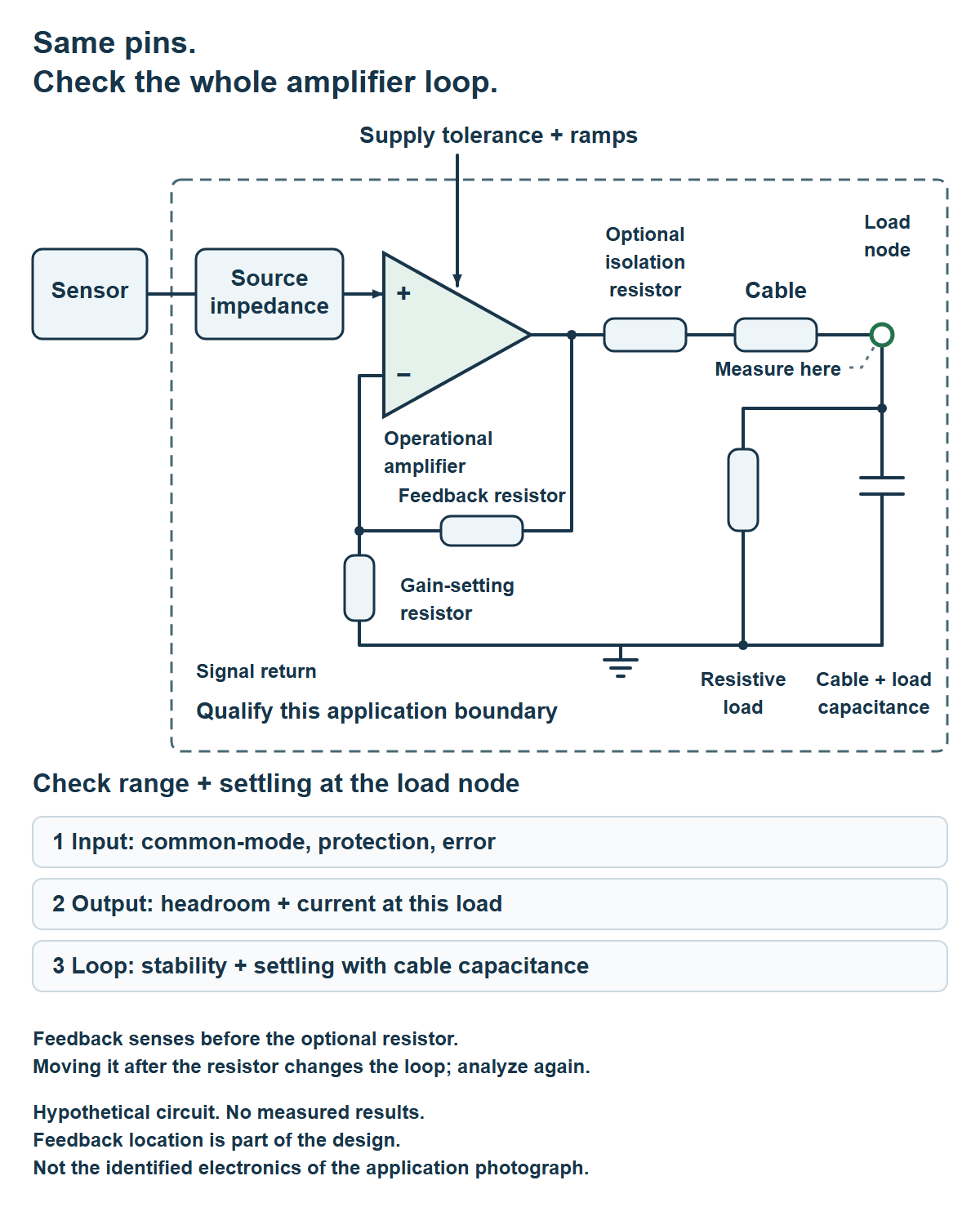
Consider a hypothetical operational amplifier (op amp), a high-gain amplifier used with negative feedback to set circuit behavior. Check input common-mode voltage—the average of its two input voltages—and the allowed differential input, the voltage difference between those two inputs. Check output headroom, the distance from each supply rail needed to deliver the required voltage at the stated load.
Include source impedance, input error, protection behavior and noise gain, the closed-loop gain seen by an input-referred voltage error. Closed-loop means feedback is connected; input-referred expresses the error as an equivalent voltage at the amplifier input.
With the intended cable and load, test stability and settling: entering and staying inside the allocated error band after a transition. Include supply ramps, relevant input steps, load changes and fault recovery.
In Figure 1, feedback senses before an optional isolation resistor. Load current creates a voltage drop across that resistor. Measure at the load; moving the feedback connection changes the loop and requires new analysis. Texas Instruments (TI) on settling illustrates why the disturbance and observation point matter.
Figure 1 · On a small screen, scroll the diagram horizontally or open the full diagram.
A multiplexed converter with a shared driver
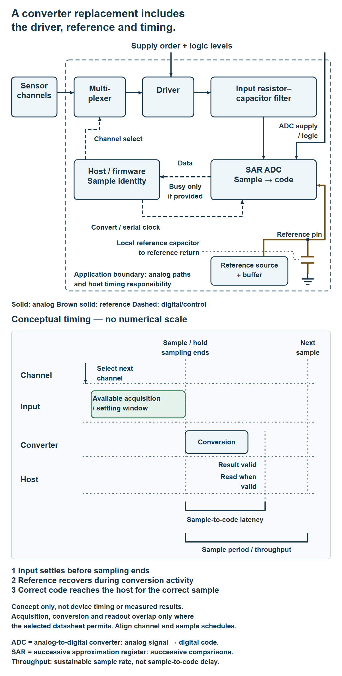
A multiplexer selects one sensor channel at a time. An analog-to-digital converter (ADC) turns its voltage into a digital code. A successive approximation register (SAR) ADC does this through successive comparisons. Its acquisition interval is the time available for the sampling input to acquire and settle to the signal.
Test demanding channel-to-channel transitions with the actual source, driver and input resistor-capacitor filter. TI’s multiplexing brief explains how some amplifier input-protection structures can disturb settling. Analog Devices’ driver example connects driver settling to acquisition time. Both describe particular architectures; their examples do not set universal limits.
Check the reference separately. Its nominal voltage alone does not show whether it recovers under conversion activity; Analog Devices’ reference discussion distinguishes dynamic demand from average current. A reference buffer is an amplifier that supplies the reference pin’s changing current demand.
Then verify channel identity, conversion control and data readout in firmware. Sample-to-code latency is the delay from the sampling instant to a usable code; throughput is the sustainable sample rate. Follow the selected device’s timing rules. A busy signal, if provided, indicates its conversion state according to that device’s rules.
Figure 2 · Scroll horizontally on a small screen or open the full diagram.
4. Request quality, change and supply evidence
Keep component reliability qualification, board-level application validation, incoming-lot acceptance and end-equipment approval distinct. Ask for the reports relevant to the exact product and grade, their scope, traceability and unresolved exceptions.
A product change notification (PCN) explains a supplier’s announced change. TI’s policy and 3PEAK’s policy give examples of information to request: affected products, the change, timing and supporting qualification or impact information. A policy page cannot replace the candidate’s actual records.
China-linked sourcing adds a channel to investigate. 3PEAK describes itself as a fabless company in China; its distribution directory lists Anglia for Europe, the Middle East and Africa. Fabless describes a business that designs chips and outsources wafer fabrication. These are attributed company and channel facts. They establish neither manufacturing locations nor available stock, delivery commitments or suitability for your board.
5. Record the decision and its requalification triggers
Use one evidence-to-test record. Assign each open item to an owner before samples move toward release.
| Evidence to retain | Test or review | Suggested owner |
|---|---|---|
| Exact codes, revisions and conditions | Resolve specification differences | Component engineer |
| Board, cable, load and measurement setup | Range, stability, settling and recovery | Analog designer |
| Converter schedule and firmware revision | Acquisition, reference recovery, sample identity | Firmware and analog leads |
| Reports, lot traceability and change records | Check scope and evidence gaps | Quality lead |
| Authorized channel and order confirmation | Verify supply commitments separately | Procurement lead |
Our proposed decision aid has four outcomes: hold for missing evidence; reject a hard requirement conflict; evaluate against an agreed plan; or release for the approved application and revisions after acceptance. A hold stays open until evidence resolves it or the authorized decision owner records a specific risk disposition.
Attach the signed decision, test records, exceptions and requalification triggers. Changes to the board, firmware, source, cable, load, operating envelope or supplier process evidence should prompt a proportionate review. Start the next candidate comparison by writing that test boundary.
Continue with planning an analog IC production handoff for test and traceability responsibilities, or the analog and power circuits behind radio-frequency systems for another system-level view of component choices.
Selected primary sources
- TI, SBOT040C (2022) — multiplexed amplifier input behavior.
- Analog Devices, AN-1499, Rev. B (2017) — driver settling and acquisition in its example circuit.
- Analog Devices, AN-931, Rev. 0 — dynamic reference loading; original publication date unconfirmed.
- TI, SLYT817 (2021) — input and output transient settling.
- TI, product change notification policy — information accompanying changes.
- 3PEAK, product change policy — affected-product and impact information.
- 3PEAK, company page — attributed fabless-in-China description.
- 3PEAK, distribution directory — current Anglia listing.
The two cases are hypothetical engineering examples, with no specific replacement pair or measured qualification result. Manufacturer application notes support circuit principles; each selected part still requires current documents and application-specific acceptance criteria.
Please link to this article when sharing. Contact us for permission to republish the full article.