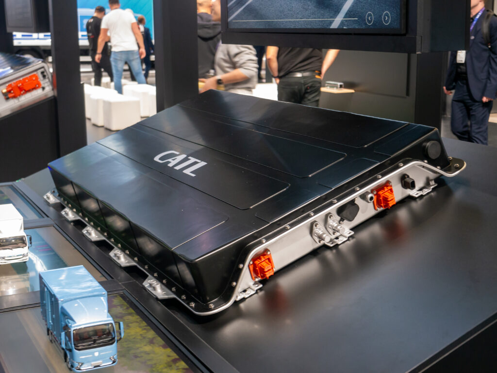
CATL battery pack displayed at IAA Transportation 2024 in Hanover (16 September 2024). Photo: Matti Blume / Wikimedia Commons, CC BY-SA 4.0. Displayed without cropping or alteration. Application context; internal protection circuitry is not shown.
Switch on an electric vehicle (EV) and its high-voltage traction battery pack has to connect to the inverter, the power electronics that turn the pack’s direct current (DC) into the alternating current the motor uses. Inside it sits a DC-link capacitor, a large capacitor bank that smooths the DC supply. When empty, it draws a surge of current the instant a switch closes. This article on EV traction-battery protection follows that moment, and its opposite: what must happen when something goes wrong and the pack has to let go. For the control chips around the same inverter, see the inverter control IC power and analog stack. Here, an IC, short for integrated circuit, is a small chip that packs many electronic parts into one package.
Three takeaways
- A traction pack needs separate protection functions: a gentle first connection, routine switching, fault interruption and sensing.
- Detecting a fault is only the start. A physical device, rated for the actual conditions, must open the circuit.
- Ask suppliers for evidence on the whole chain, from sensor to interrupter to leftover energy, not one chip’s response time.
Why a connected battery needs several protection functions
A traction pack supplies large current at high voltage and can fail in different ways: a surge at first connection, a short circuit in the vehicle, or leakage between the high-voltage side and the chassis. Each needs a different response, so split the job into five roles:
- Sensing: measuring voltage, current and insulation resistance, which shows how well the high-voltage side is electrically separated from the chassis, that is, how small the leakage is.
- Decision: logic that judges whether a reading is abnormal.
- Driver: a circuit that supplies the power needed to command a switch or an igniter.
- Physical interrupt: the device that actually opens the circuit.
- Residual energy: whatever energy is still stored after the circuit opens.
These parts often sit in a battery junction box (BJB) or battery disconnect unit (BDU), the assemblies that hold a pack’s switching and protection hardware. Suppliers may use the two names for different sets of hardware, so ask what functions a box actually contains.
Precharge protects the connection to the inverter’s DC-link capacitor
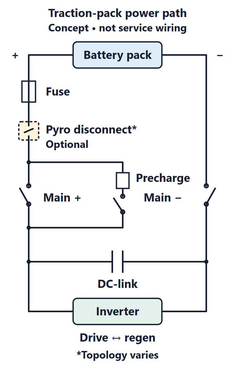
Precharge means bringing the DC-link capacitor up toward pack voltage through a current-limiting path before the main connection closes. Texas Instruments’ (TI) precharge reference design (September 2024) describes charging the capacitor to battery voltage to minimize the inrush current, the sudden surge, when the main contactors close. A contactor is a heavy-duty, electrically operated switch for high-current paths. It also notes that too much inrush can weld the contacts together.
A common arrangement puts a resistor and a switch in a branch around the positive main contactor. Three cautions:
- Return path. Current only flows if the negative main contactor, or an equivalent return path, is closed. The closing order depends on the system.
- Monitored progress. Treat precharge as a monitored process, not a fixed timer. The controller should watch the voltage rise and abort on abnormal progress, such as a shorted load or a stuck switch. Limits and failure response belong to your system.
- Pulse thermal budget. The resistor and switch absorb energy in every precharge. Check their pulse and repeated-pulse ratings, not only average power.
Precharge does not prevent every way a contactor can weld. And TI’s stated goal of a solid-state relay (a semiconductor switch) applies to the precharge branch only; it is not evidence of a solid-state breaker for full traction current.
Contactors, melting fuses and pyro disconnects have different jobs
The main contactors connect and disconnect the pack in normal operation. Switching a load is not the same as opening every fault. Establish each contactor’s and interrupter’s rated DC breaking envelope under your system’s prospective fault current (the current that would flow at the fault location without a protective device limiting or interrupting it), voltage, current direction and circuit inductance (the property that opposes changes in current and stores energy in a magnetic field while current flows).
A melting fuse reacts to the thermal effect of an overcurrent, according to TI’s 2025 battery-disconnect article (revised April 2025). A pyro-fuse, or pyrotechnic disconnect, breaks the connection on command, and the same article says it requires an electronic driver to send that signal. The initiator, also called a squib, is the small pyrotechnic igniter that the driver activates.
They are not interchangeable: a fuse acts on what current does to it, a pyro disconnect on a decision made elsewhere. Do not assume a fuse always clears before a contactor, or the reverse; coordination needs supplier evidence.
Direction matters too. In regenerative braking, the motor acts as a generator and returns energy to the pack, so current reverses. A drawing with arrows both ways does not mean every interrupter is rated for both.
Sensing and drivers connect fault detection to physical interruption
A pack monitor is a chip that measures pack-level quantities such as voltage and current. TI’s 2023 article describes a dedicated signal path in such a monitor for overcurrent, and notes that insulation resistance between the high-voltage and low-voltage domains must be measured. Insulation supervision observes; it does not interrupt current.
Sensing, decision, driver command, initiator action and mechanical clearing each take time; there is no universal total.
Galvanic isolation is an electrical separation that lets signals cross with no direct conducting path. Where that boundary sits depends on the architecture; do not assume two products share a reference domain or that all isolators are equivalent.
Keep driver ratings apart from pack ratings. The DRV3901-Q1 squib driver page (datasheet listing October 2023) gives voltage ratings for the driver’s own auxiliary supply, not the pack’s blocking voltage or current capacity.
Publicly documented vendor examples divide these functions differently. TI describes a separate pack monitor and driver. NXP describes its MC33777 as integrating measurement, diagnostics and autonomous control of two pyrotechnic switches, without the main processor stepping in (page undated, accessed 25 October 2026). These are two example arrangements, not drop-in replacements for one another. Either chain still needs evidence on supply energy and driver-initiator compatibility.
Finally, opening the pack connection does not discharge the DC-link capacitor; TI’s precharge design lists a discharge path as a separate element. Nor does it remove the energy inside the cells or guarantee against thermal runaway, a cell’s self-heating failure. Residual energy is its own design item.
Supplier evidence: a China ecosystem example and a generally applicable checklist
Protection hardware is a supply layer apart from the monitor and driver chips: chip vendor, pack integrator, contactor, fuse or pyro supplier, and test or qualification provider.
As one example, Xi’an Sinofuse Electric lists power fuses, pyro fuses, smart fuses, relays, current sensors and intelligent BDU solutions for new energy vehicles on its solutions page, which gives a Xi’an address (page undated, accessed 25 October 2026). This portfolio example covers protection hardware and BDU assemblies, not monitor or driver ICs. It says nothing about the company’s other business. A public product list does not establish part equivalence, qualification, availability, driver compatibility, capacity or any relationship.
The checklist below applies to any supplier, anywhere:
- DC breaking data at your voltage, current, direction and inductance.
- Driver and initiator compatibility, in writing.
- Which tests were run, and by whom.
- How changes are notified.
Map the complete fault-to-action chain before choosing parts
Fill in one row per fault. An empty cell is a question for a supplier.
| Fault or event | What senses it | What decides | What drives | What physically interrupts | Evidence to request |
|---|---|---|---|---|---|
| Precharge progresses abnormally | Pack and DC-link voltage readings | Controller compares progress with system limits | Command to stop the precharge switch | Precharge switch; the positive main contactor stays open until precharge succeeds. Abort handling and the negative-return state depend on the architecture and the fault | Resistor and switch pulse-energy budget, return path, abort response |
| Short circuit or overcurrent | Current sensing | Monitor or controller threshold logic | Contactor driver or pyro driver, if used | Fuse, pyro disconnect or contactor, within its rating | DC breaking rating for actual conditions; coordination data |
| Insulation fault to chassis | Insulation resistance measurement | Controller classifies the reading | System-defined response | None by itself; supervision does not interrupt | Defined response and who owns it |
| After disconnect | Voltage across the DC link | System logic | Discharge path, if provided | Not applicable | How stored energy is removed and verified |
Next step: fill the table for your pack concept and send every blank to the relevant supplier before part selection. For related charging safety, see megawatt charging system safety.
Selected sources
- Texas Instruments, precharge reference design TIDUF73, September 2024 as displayed.
- Texas Instruments, battery-disconnect article SSZTCU8A, revised April 2025.
- Texas Instruments, article SSZT047, January 2023.
- Texas Instruments, DRV3901-Q1 product page, datasheet listing October 2023, accessed 25 October 2026.
- NXP, MC33777 product page, undated, accessed 25 October 2026.
- Xi’an Sinofuse Electric, new energy vehicle solutions page, undated, accessed 25 October 2026.
Please link to this article when sharing. Contact us for permission to republish the full article.