
Suppose a supplier proposes changing the joint under a silicon carbide (SiC) power chip from solder to silver sintering, which bonds fine silver particles together with heat and sometimes pressure. SiC is a semiconductor material used in power devices. This is a hypothetical case.
Silver sintering can be attractive because the joint is built from silver rather than a lower-melting solder alloy. Whether it helps the module you are reviewing depends on evidence for your own stack, the layers from chip to substrate, so the practical answer is to ask for matching records and matching tests. Qualification, meaning evidence that a part meets defined application requirements, is where that evidence is judged.
Three takeaways
- Name the exact joint being changed and the full stack around it.
- Compare reliability evidence only under matching conditions.
- Give each process record and each open evidence gap a named owner.
The joint is part of the power module
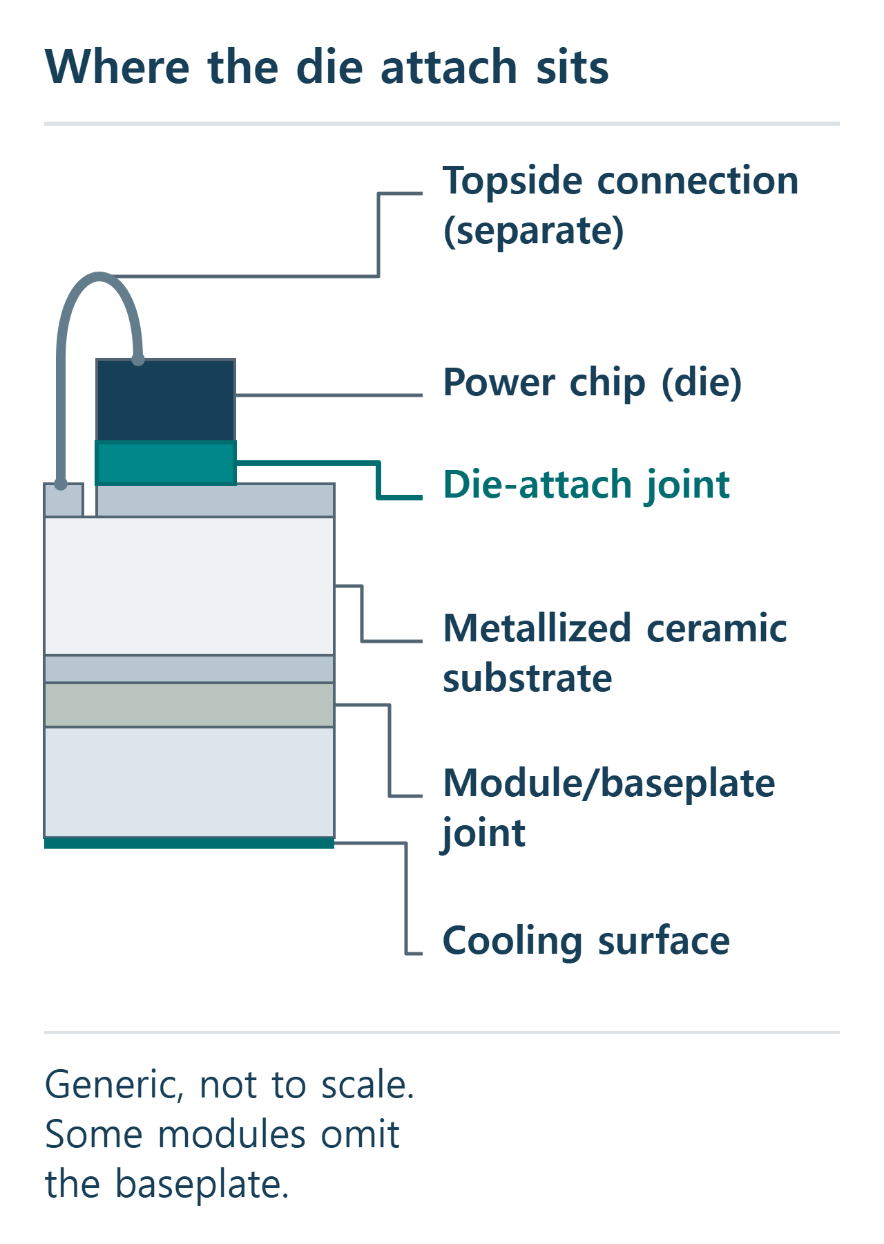
A power module packages one or more chips with their connections and cooling. In the ceramic-substrate module illustrated here, each chip, called a die, is bonded to a metallized ceramic substrate: a ceramic plate (the supporting structure) whose surface carries a metal layer, the metallization, used for bonding and electrical connection. That chip-to-substrate joint is the die attach. It holds the die in place, carries heat away from it and, where the chip’s back side is an electrical terminal, carries current.
Two other connections are easy to confuse with it. In this example the substrate is joined to a baseplate or cooling surface, a separate module-level joint, although some module types omit the baseplate. On top of the die, wire bonds or similar contacts form the topside connection. A failure at any of these can look alike in a module test, so naming which joint a proposal changes comes first.
What changes when solder becomes a sintered joint
Soldering joins parts with a filler alloy, the solder, that melts and then solidifies. Sintering consolidates fine metal particles, here silver, into a solid joint using heat and, in some routes, pressure. Fraunhofer IISB (Institute for Integrated Systems and Device Technology), a research institute, describes pressureless and pressure-assisted sintering as separate routes. Heraeus, a materials supplier, distinguishes die attach on a ceramic substrate from module attach on a baseplate or heatsink, and also offers a non-pressure silver die-attach paste.
Suppliers are applying sintering to SiC modules. Toshiba, for example, announced on September 24, 2026 its IX800FXF2YMS4 module and said it uses silver sintering bonding at the SiC chip bonds, listing railway among its applications. That is a dated vendor example of the question reaching current products; it says nothing about which module any particular train uses.
The limits belong to the part. A pressure-assisted route applies pressure while the joint sinters, so the equipment must apply and control it; a pressureless paste suits the stacks and conditions its supplier has shown. Settings proven for one chip, finish and substrate apply to that combination. Checks therefore assess porosity (tiny voids inside the joint; some is expected in a sintered joint, so the question is whether it stays within agreed limits) and delamination (separation at an interface), and they do so in your stack.
Compare the same stack and the same test
A sintered result means little without the stack it came from. Record the die size and thickness, the finish on the chip back side and on the substrate, the materials, the bondline (the thickness and quality of the joint layer) and the process actually used. Fraunhofer ENAS (Institute for Electronic Nano Systems), another research institute, points out that printing parameters, drying conditions and the bond process all have to be considered.
Then match the test. Power cycling heats the chip by running current through it and lets it cool; temperature cycling changes the whole part’s temperature from outside. Each loads the joint differently, so compare temperature range, heating and cooling times, loading, sample count, failure definition and stop point. A mission profile, the stresses expected over the product’s service life, shows which test resembles your application.
A simple test piece and a finished module answer different questions. In one ENAS research project, wire-bond failures dominated die-attach failures. A module that fails first at the topside connection shows only that its die attach had not reached its own defined failure by that point under those conditions; it does not show how long the die attach would have lasted. A survivor says little unless the conditions match.
Build the supplier evidence sheet
This worksheet is our proposed method, not a supplier or standard form. Characterizing a material, controlling an assembly process and qualifying a finished module are separate evidence layers. The material-stack row mainly characterizes the material; the process-window, initial-integrity and traceability rows support process control; the baseline and cycling rows contribute to module qualification. No single row qualifies a module on its own.
| Change | Evidence to request | Responsible party | Open decision |
|---|---|---|---|
| Material stack | Die size and thickness, back-side and substrate finishes, materials, bondline | Chip, material and substrate suppliers; assembly owner | Which stack and revision is the reference? |
| Process window | Deposition, drying, bonding and pressure route, with allowed variation | Assembly owner; material supplier | Which settings and limits are released? |
| Initial joint integrity | Non-destructive inspection of each sample, cross-sections on separate parts, defect criteria, sample identity, agreed before cycling | Process owner; test laboratory | What counts as an acceptable joint? |
| Thermal/electrical baseline | How starting measurements were taken; what drift matters | Module owner; laboratory | What drift triggers concern? |
| Cycling/end-of-life evidence | Test object, samples, loading, temperatures, timing, failure mode and location (which joint failed), stop criteria | Module and test owners; customer | Does the test match the mission profile? |
| Lot traceability/change control | Links from material lots, stack revision and process records to test samples | Quality owner; suppliers; customer | Which changes reopen the evidence? |
Where local application support fits
Some of this evidence is produced at supplier application centers. Heraeus describes power-module prototyping and local testing of power assemblies to AQG 324 (Automotive Qualification Guideline 324, published by ECPE, the European Center for Power Electronics, for automotive power modules) at its Shanghai site, on both its English and Chinese pages. That is the company’s own service description; capacity, accreditation, availability, test outcomes and any relationship with ChinaSemiOps lie outside what the pages show.
The scope section of Release 04.1/2025 covers power modules for motor-vehicle converters and excludes qualification of semiconductor chips and of manufacturing processes, so AQG 324 gives no railway approval and no process certification. The worksheet applies to a supplier in Shanghai or anywhere else: the useful handoff is the same sheet, filled in by named parties.
What to settle before release
Before accepting the change, agree in writing on four things: the joint and stack being changed, the reference test and its link to the mission profile, who owns each worksheet row, and which later changes reopen the question. Where evidence comes from a different stack or test, record the gap and its owner and leave the conclusion open. Then ask for the same sheet for the incumbent solder route, so both options are judged on the same terms.
Sources
- Toshiba Electronic Devices & Storage: SiC power module announcement, September 24, 2026: a dated vendor example of silver sintering at SiC chip bonds, with railway among listed applications.
- Heraeus Electronics: sinter materials overview and its non-pressure sinter materials page: die attach versus module attach, and a non-pressure die-attach paste.
- Fraunhofer IISB: materials and processing: pressureless and pressure-assisted sintering as separate routes.
- Fraunhofer ENAS: silver and copper-tin sintering for power electronics: printing, drying and bonding parameters to consider.
- ECPE: Automotive Qualification Guideline AQG 324 (Release 04.1/2025): the guideline and its scope statement in section 1.
- Heraeus Electronics: technology and application centers (Chinese page): the vendor’s own description of Shanghai prototyping and testing.
- Joining fundamentals: STMicroelectronics AN6280 (silver particles consolidating under heat and pressure, used only for that basic mechanism), Kester FAQ and NIST Alloy Selection (solder melting and solidifying).
- Cycling fundamentals: ESPEC power cycling and rapid temperature change test pages (current-driven versus chamber-driven temperature changes; one implementation each, not a required recipe).
Please link to this article when sharing. Contact us for permission to republish the full article.